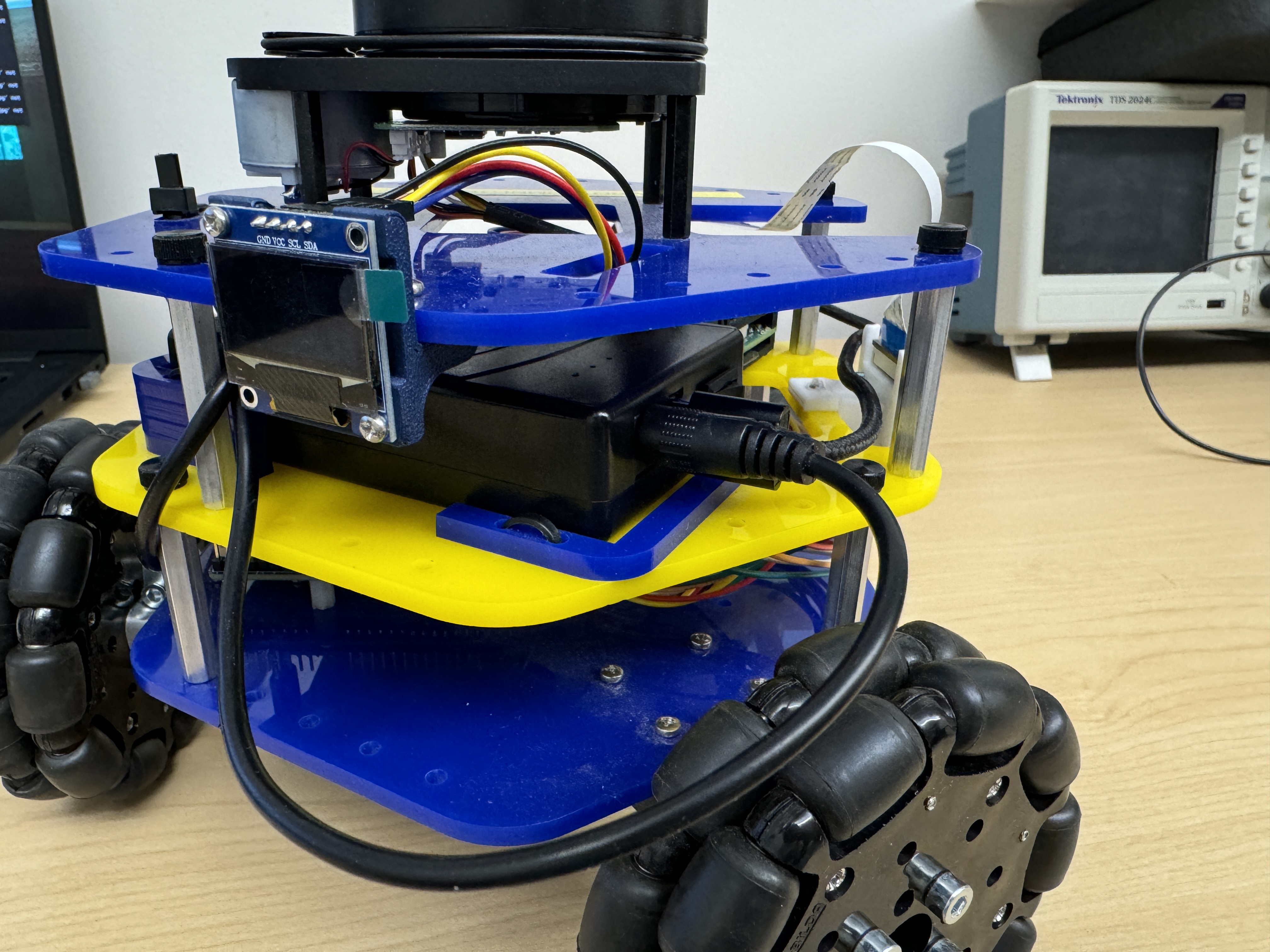
MBot Omni Assembly Guide
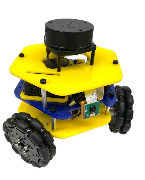
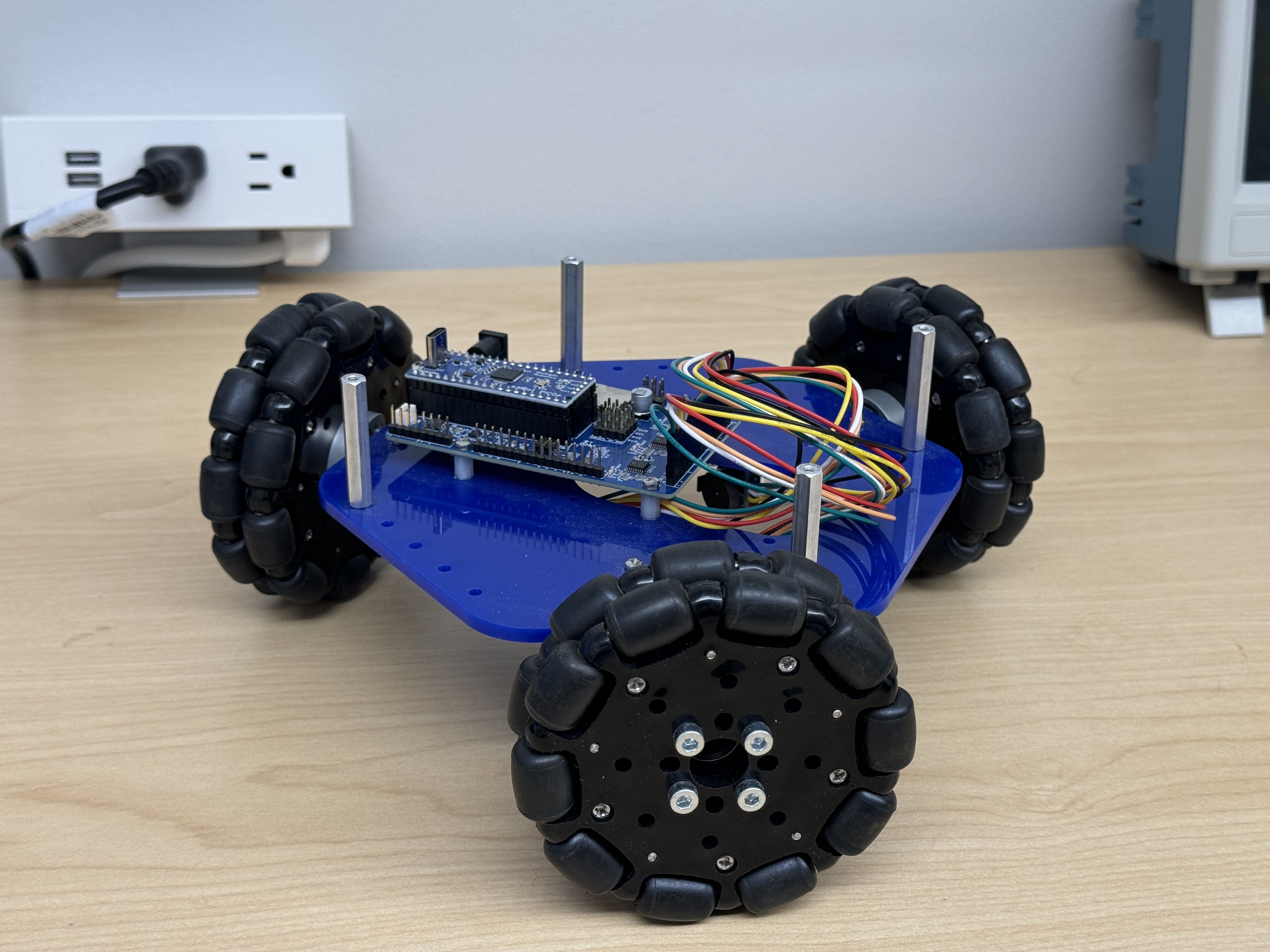
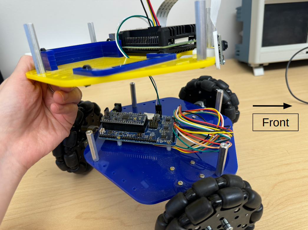
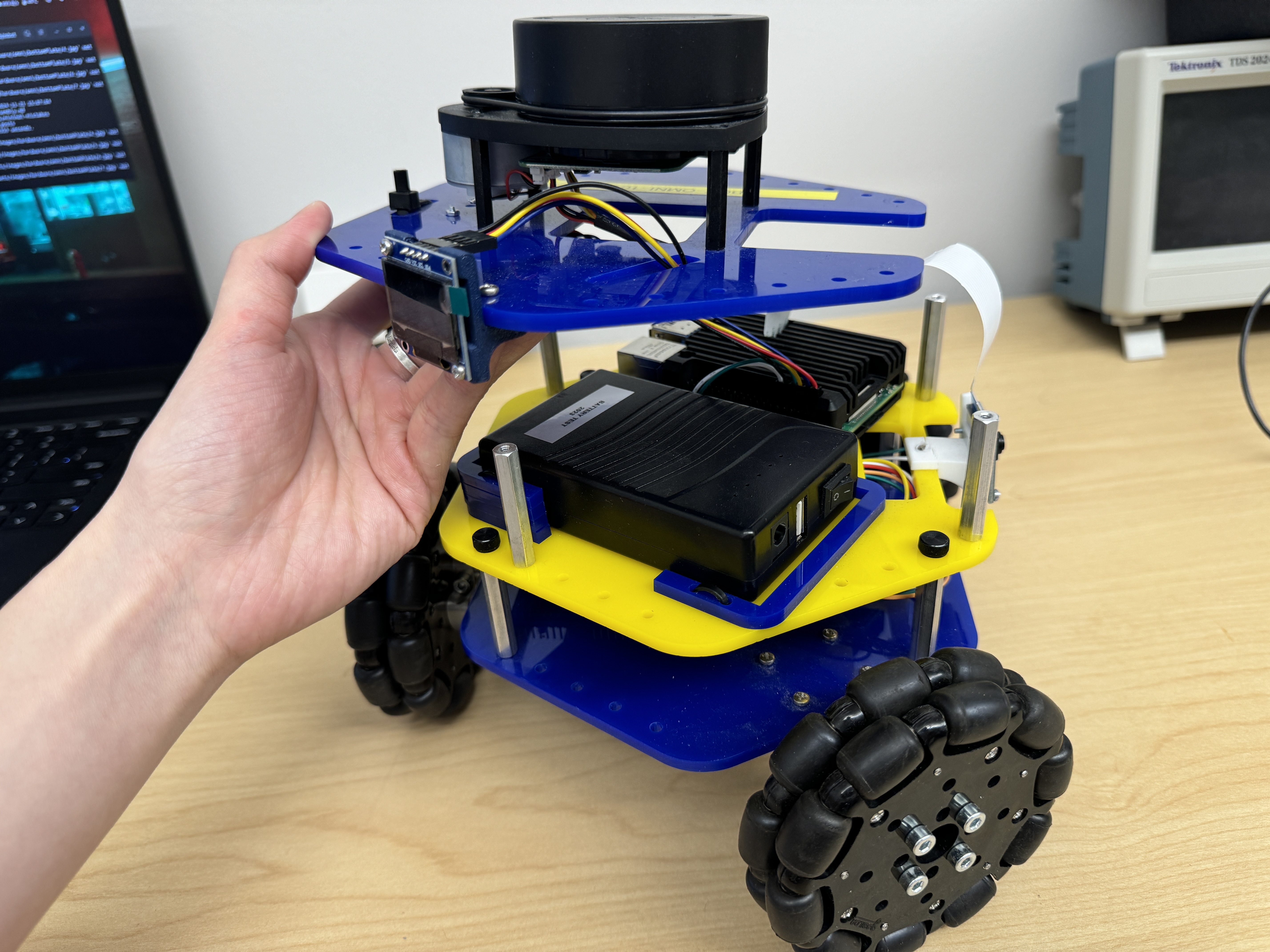
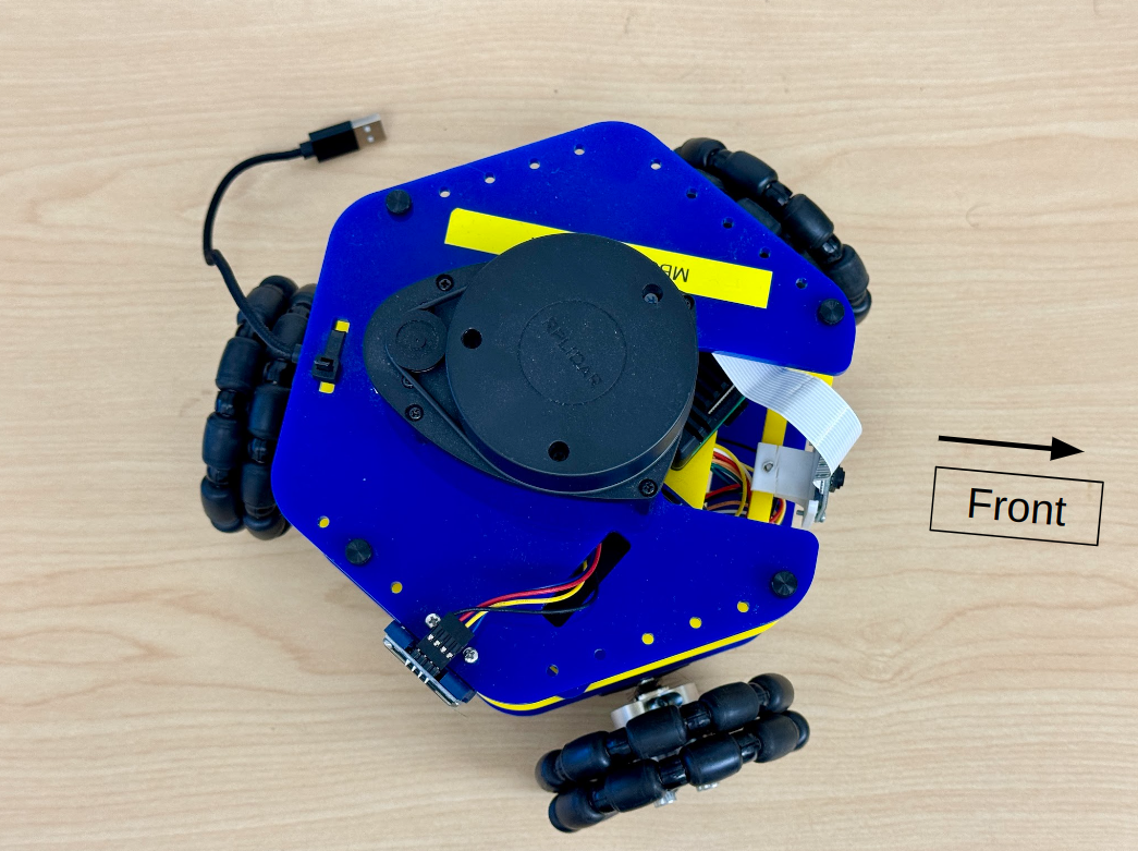
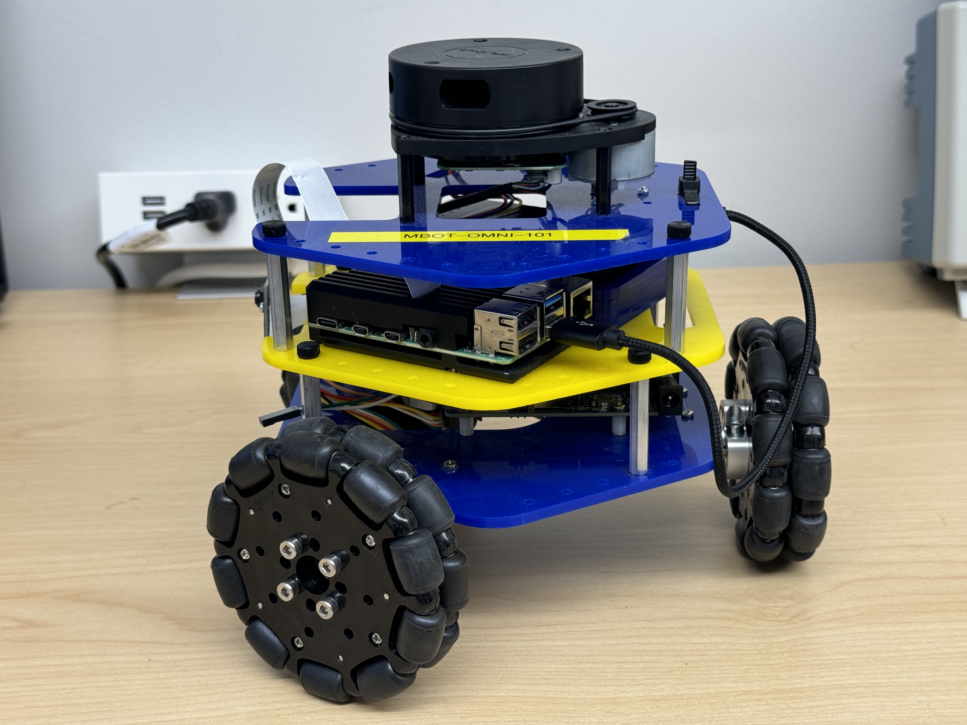
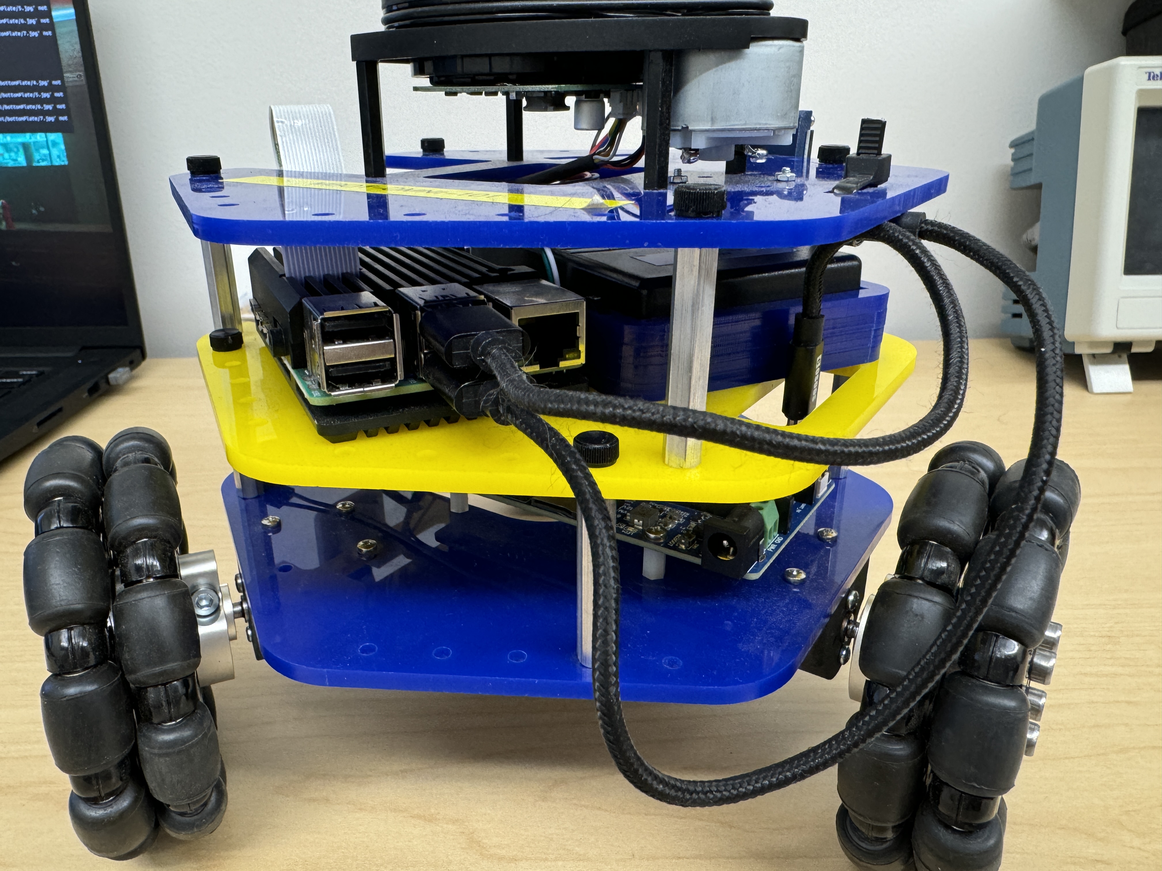
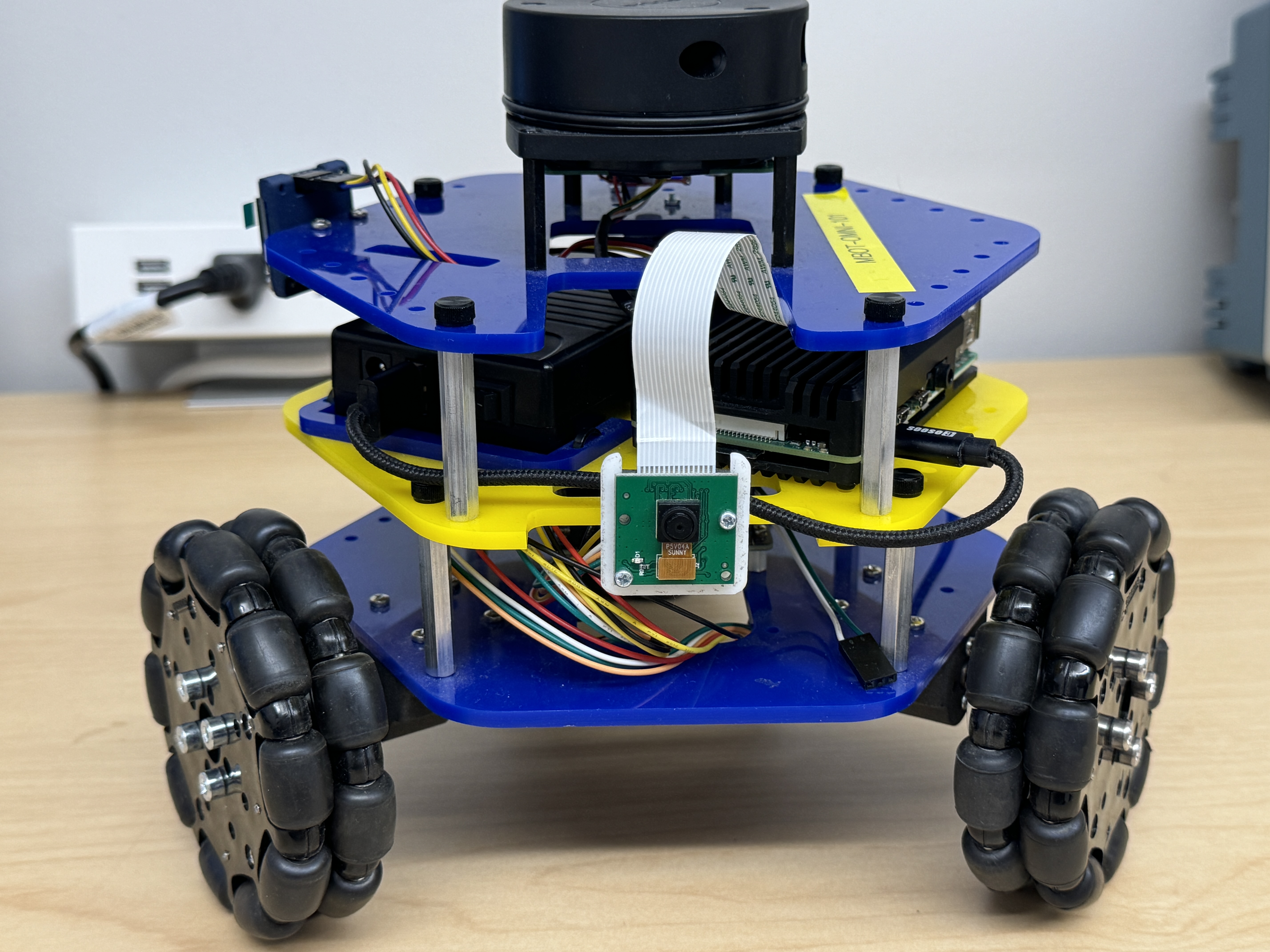
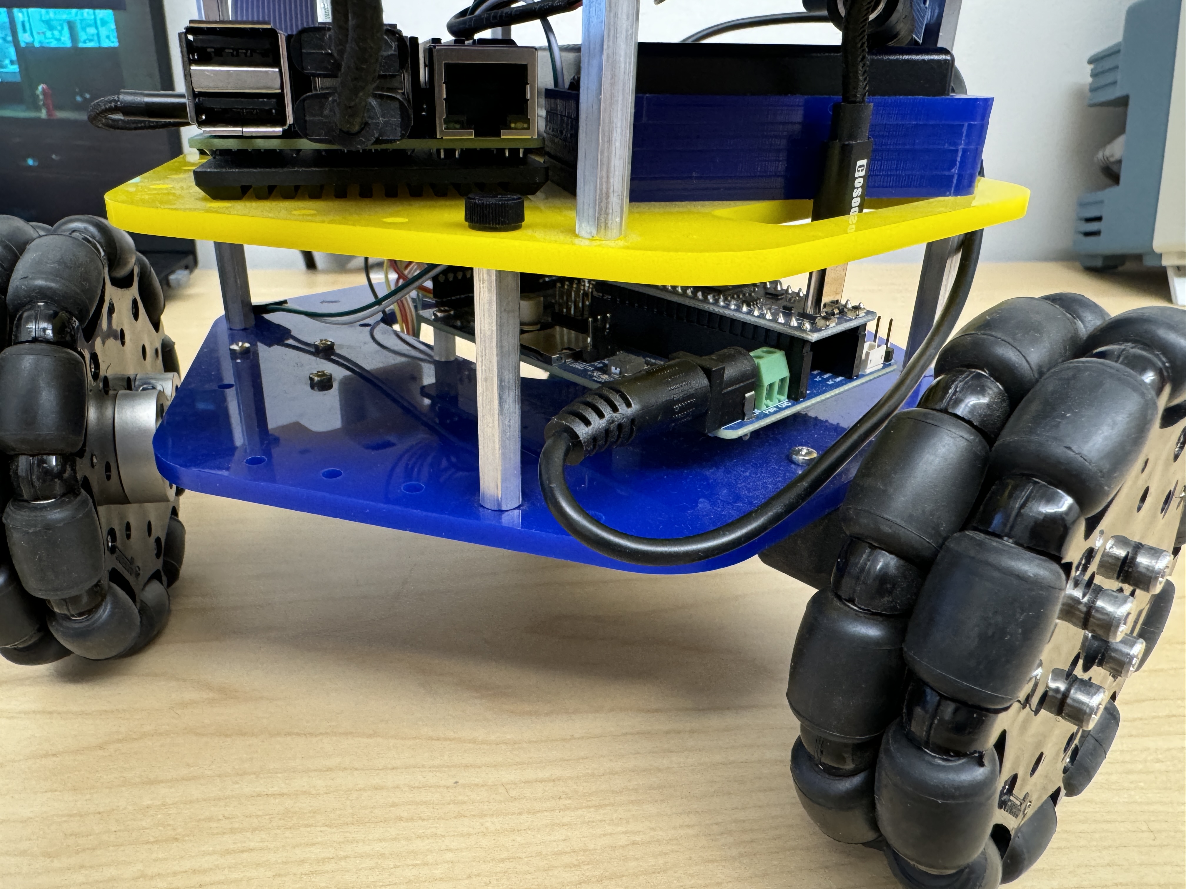
This guide will walk you through the steps needed to assemble the MBot Omni. The MBot Omni Bot is comprised of 3 sections: the bottom plate, middle plate and the top plate. Each of these plates are assembled separately first, before attaching them together to create the MBot Omni.
Bottom Assembly
1. Assemble control board and wheels
| Components | # |
|---|---|
| Robotics Control Board | 1 |
| Raspberry Pi Pico | 1 |
| Omni-wheel Sets | 3 |
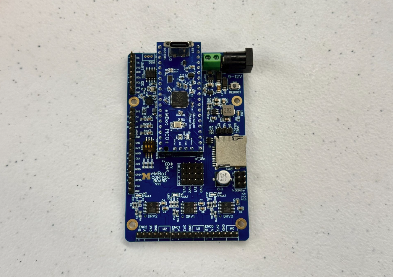
- Attach the Pico board to the control board as shown in the images below.
-
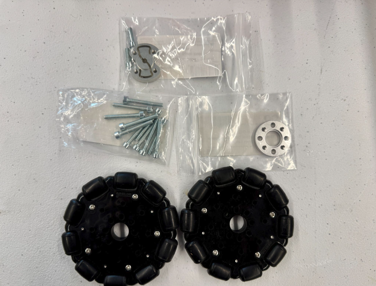
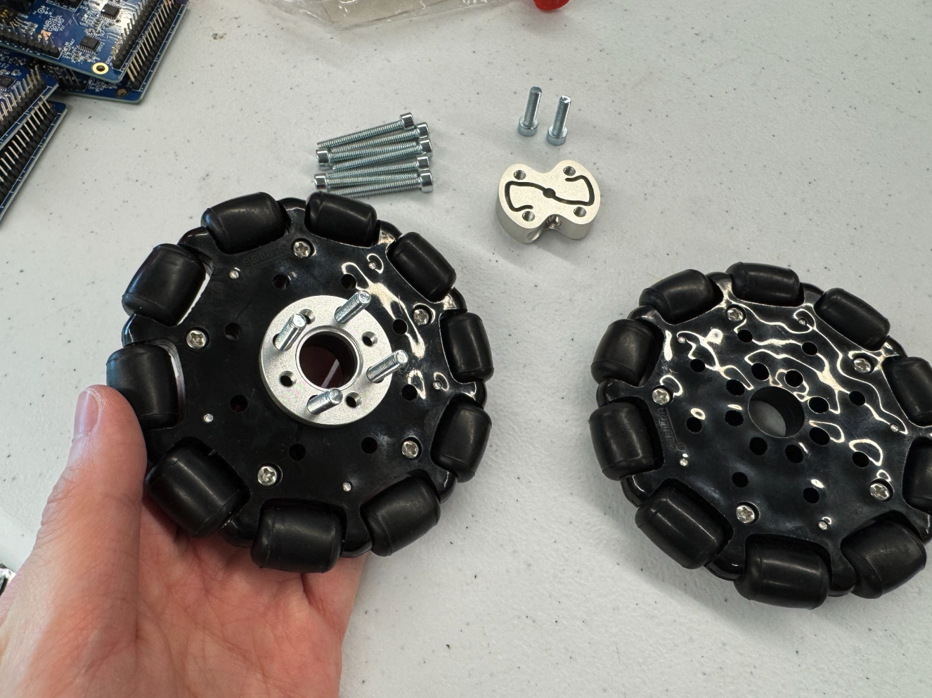
Collect all the wheel components as shown in the image below.
Note: The wheels used here have a diameter of 96 mm.
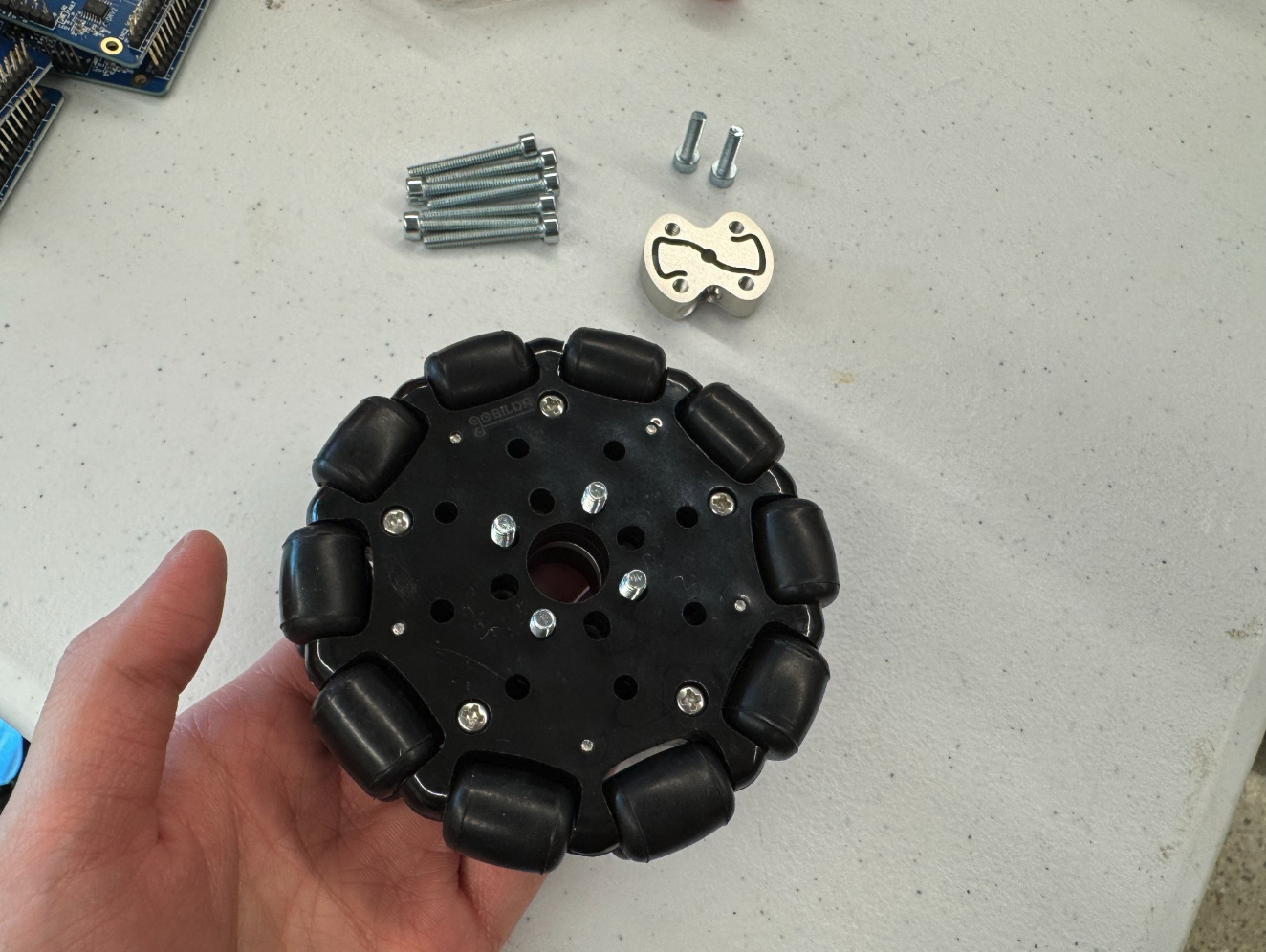
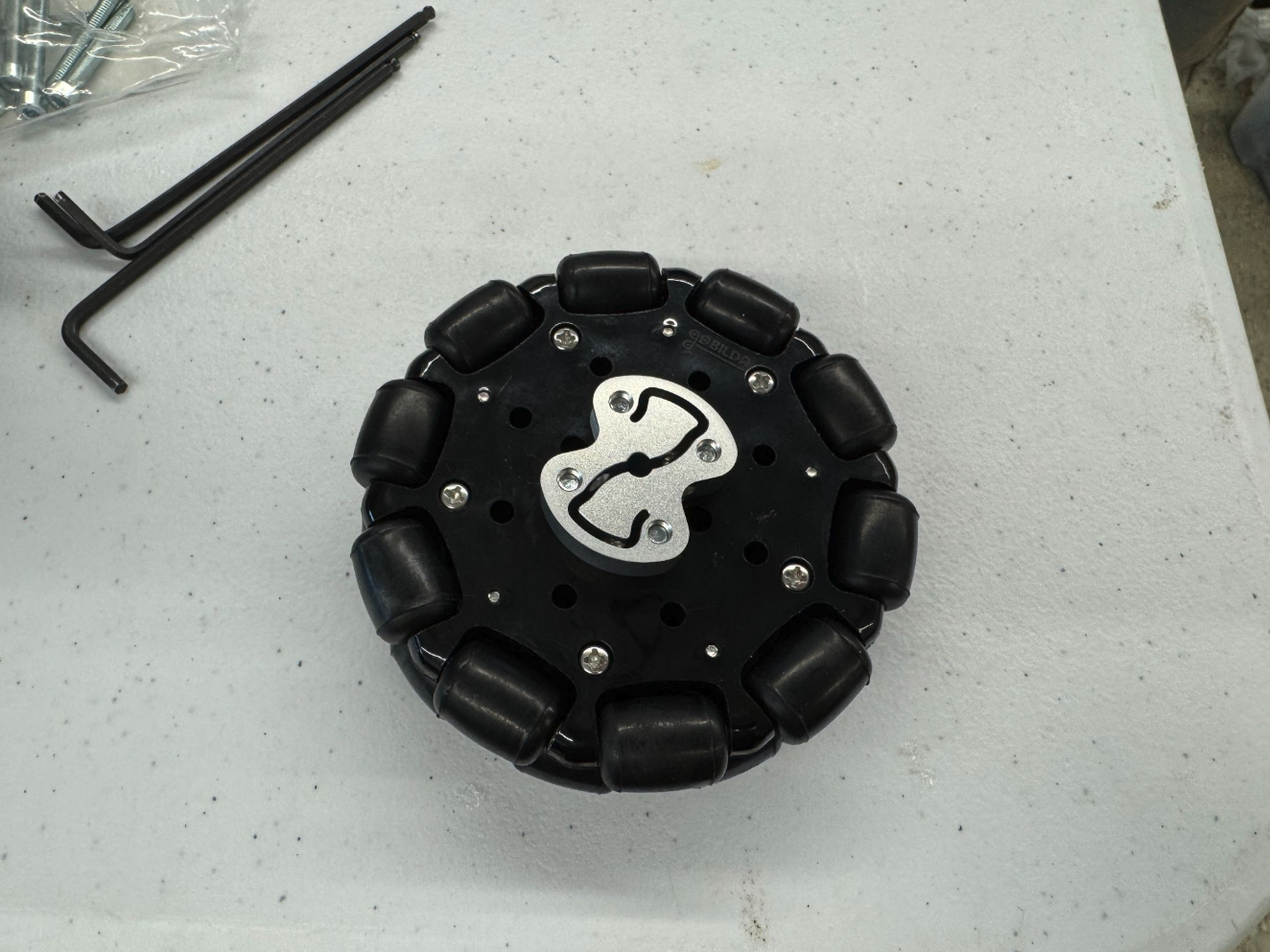
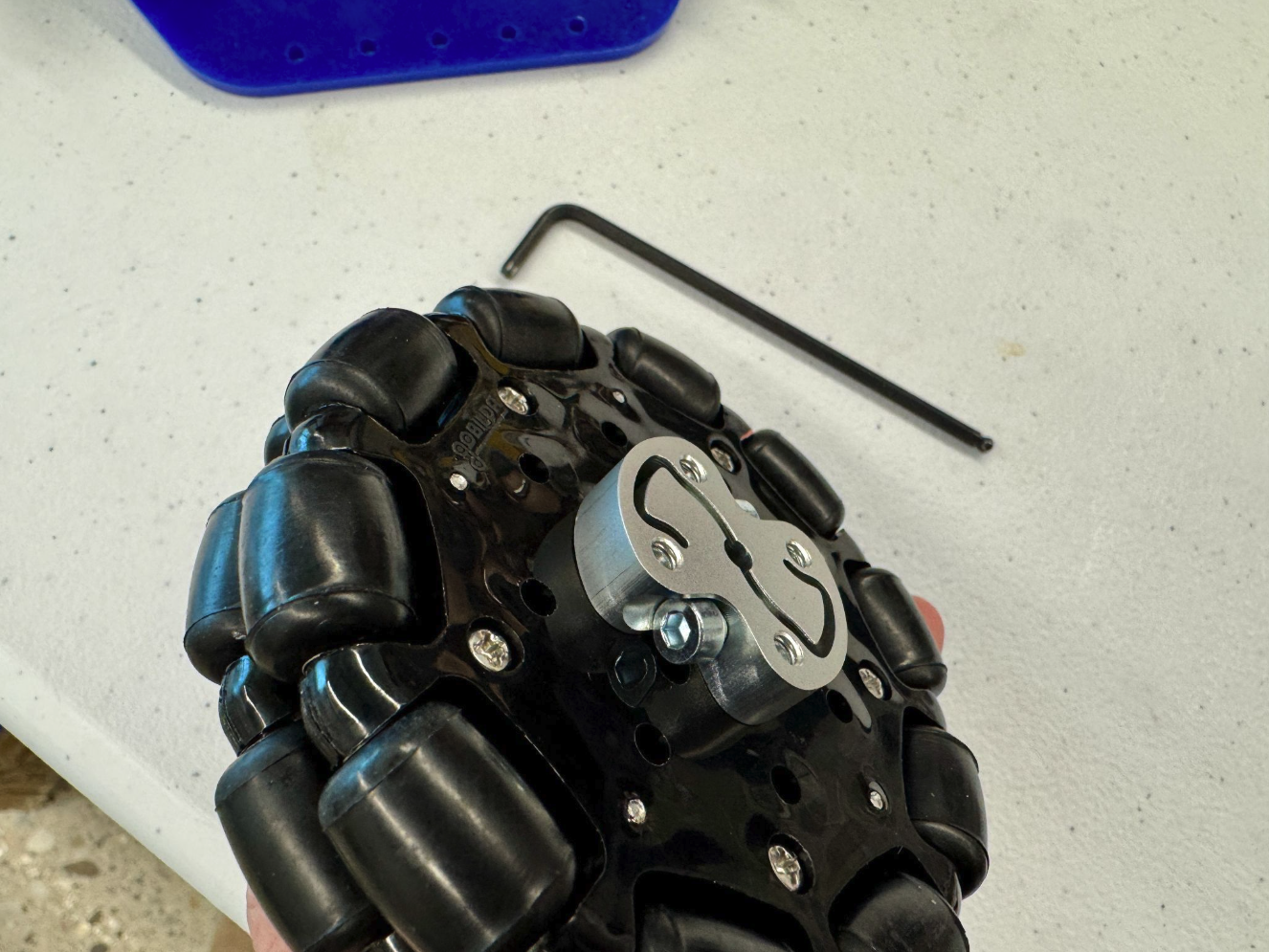
Then assemble the wheels:
- Insert four long screws through the holes in the wheel (wheel facing direction doesn’t matter).
- Stack a spacer onto the screws, then place another wheel on top.
- Add the coupler on top and tighten everything securely.
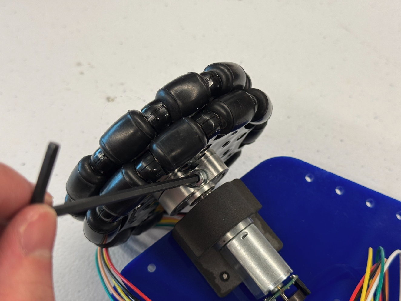
- Finally, use a hex key to attach two short screws into the coupler. These screws secure the wheel to the MBot later.
2. Attach the motor mount
| Components | # |
|---|---|
| M2.5 x 8mm Screws | 12 |
| Motor Mount (3D printed) | 2 |
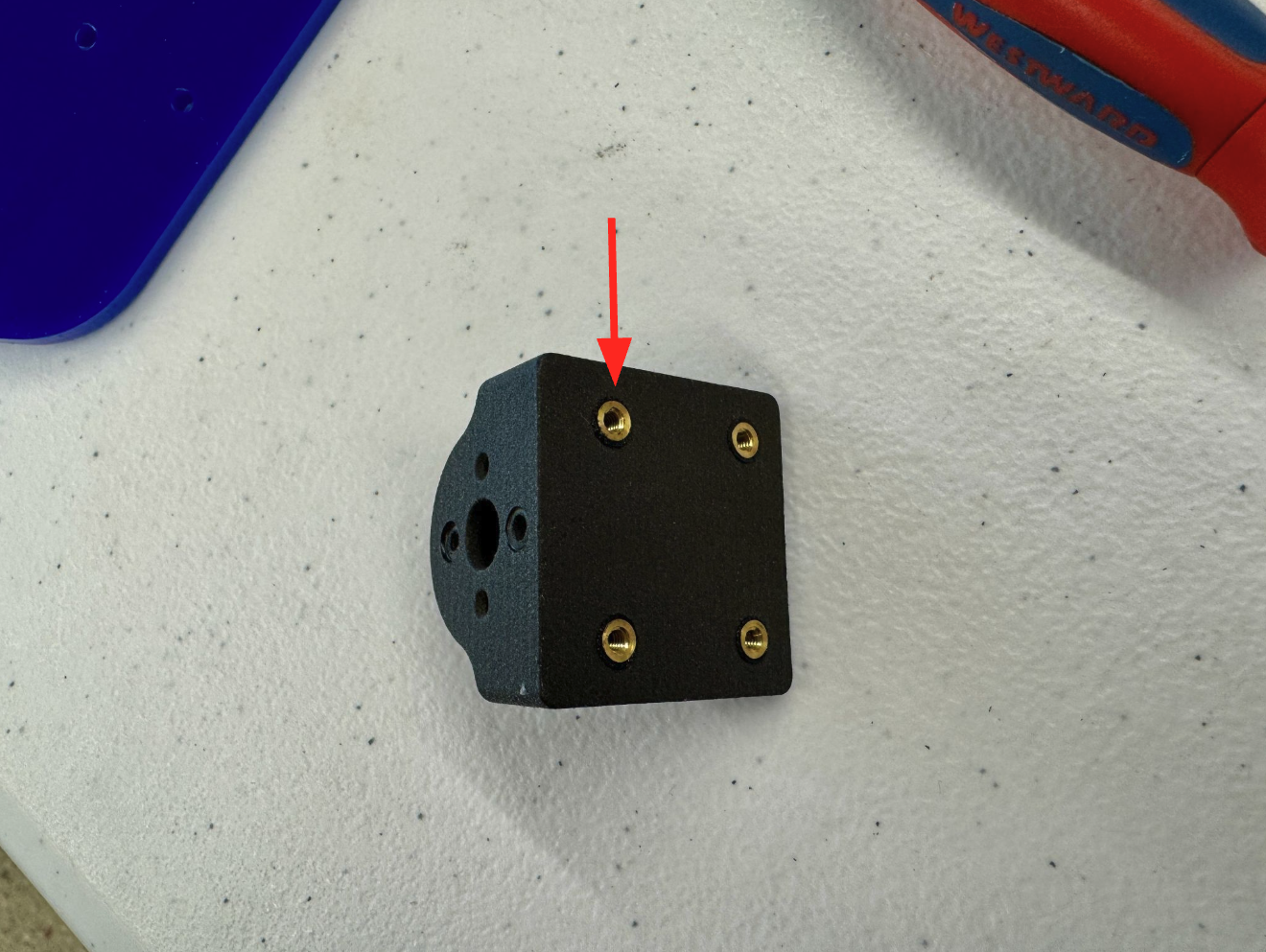
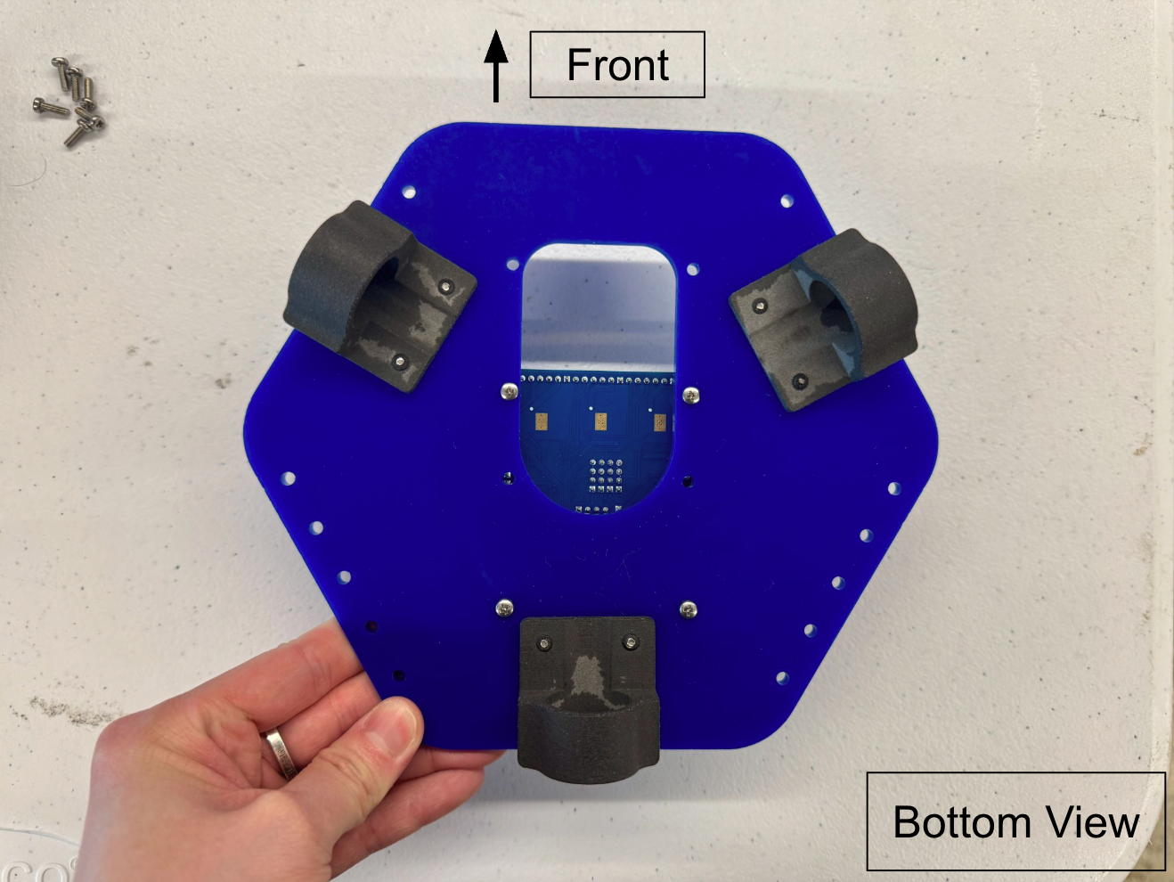
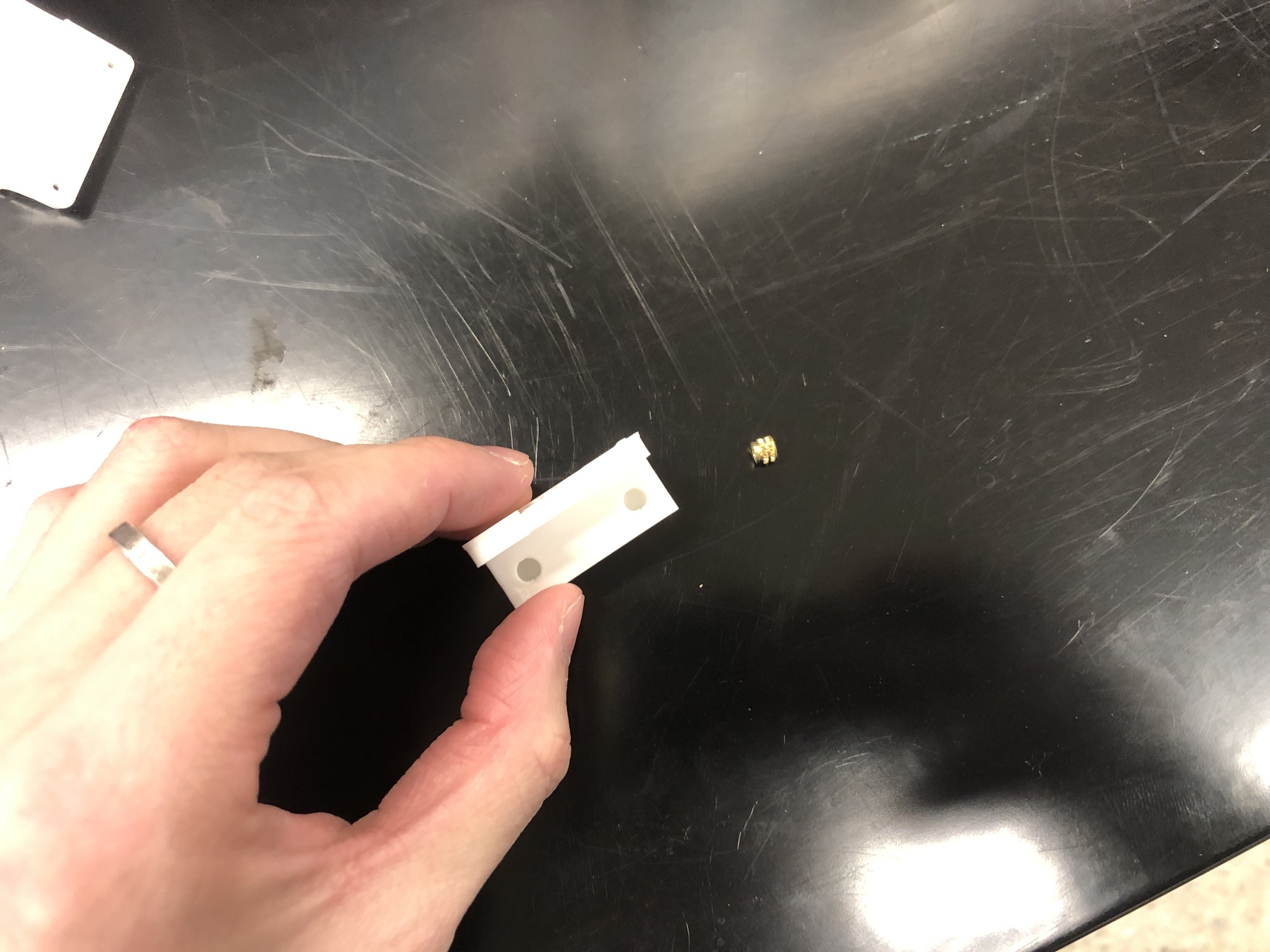
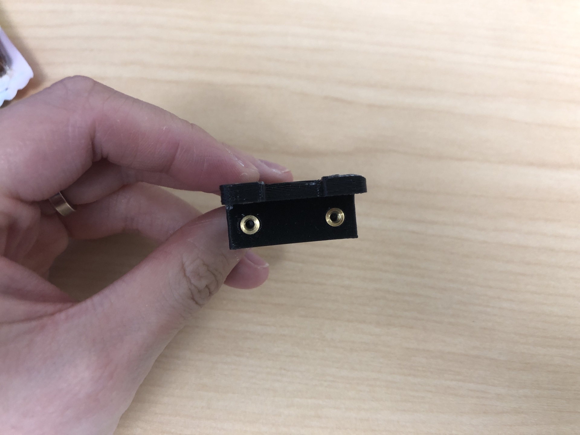
- Look at the bottom of the motor mount. If the holes don’t already have M2.5 threaded inserts (as shown in the image below), you’ll need to install them yourself:
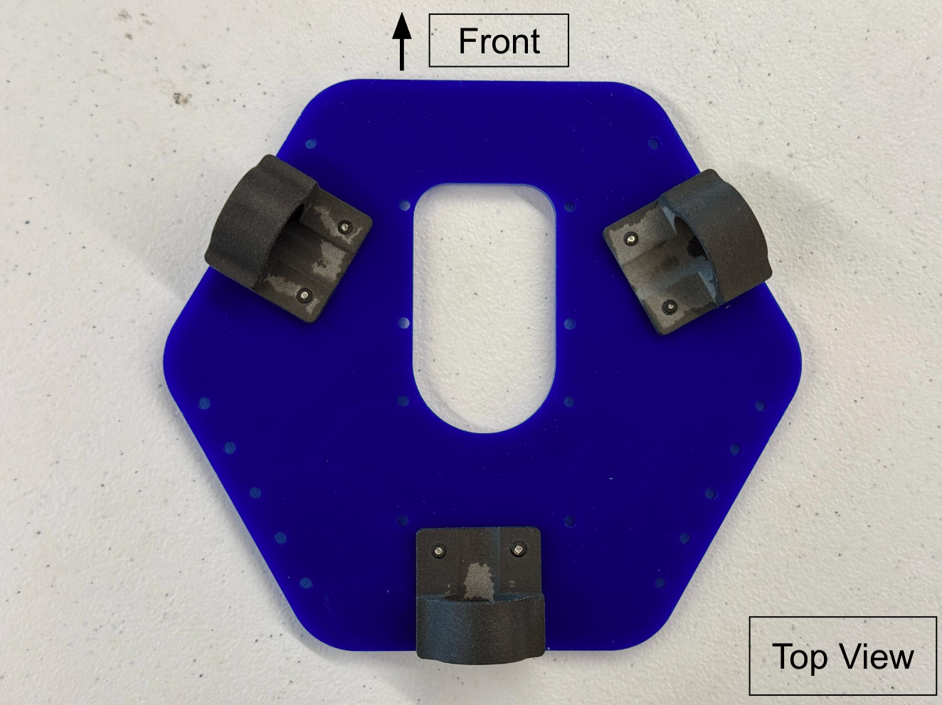
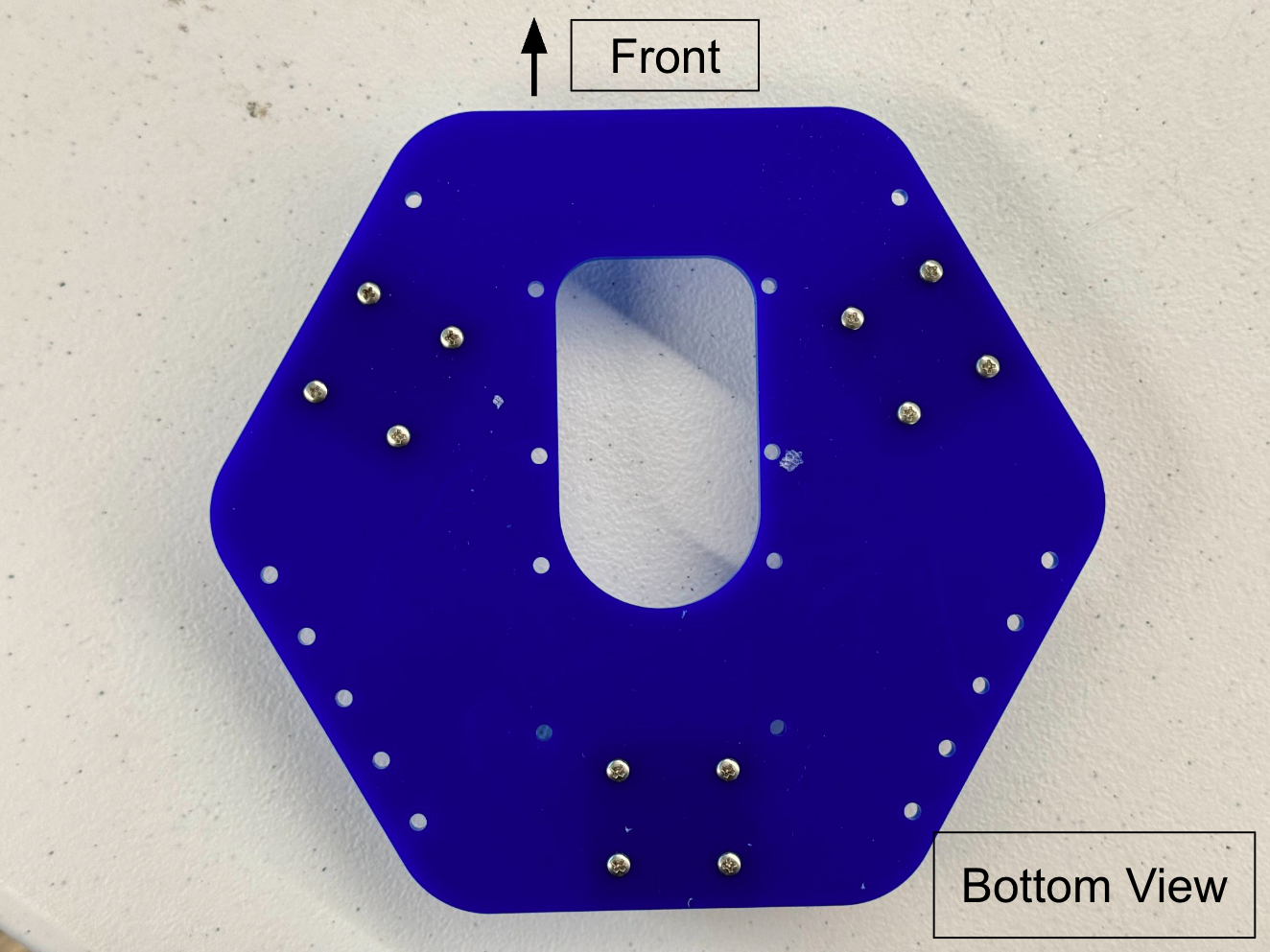
- Attach them as illustrated in the images below. When attaching the mount to the bottom plate, ensure that the slot faces inward.
3. Attach control board
| Components | # |
|---|---|
| M2.5 8mm Nylon Standoffs | 4 |
| M2.5 x 6mm Screws | 4 |
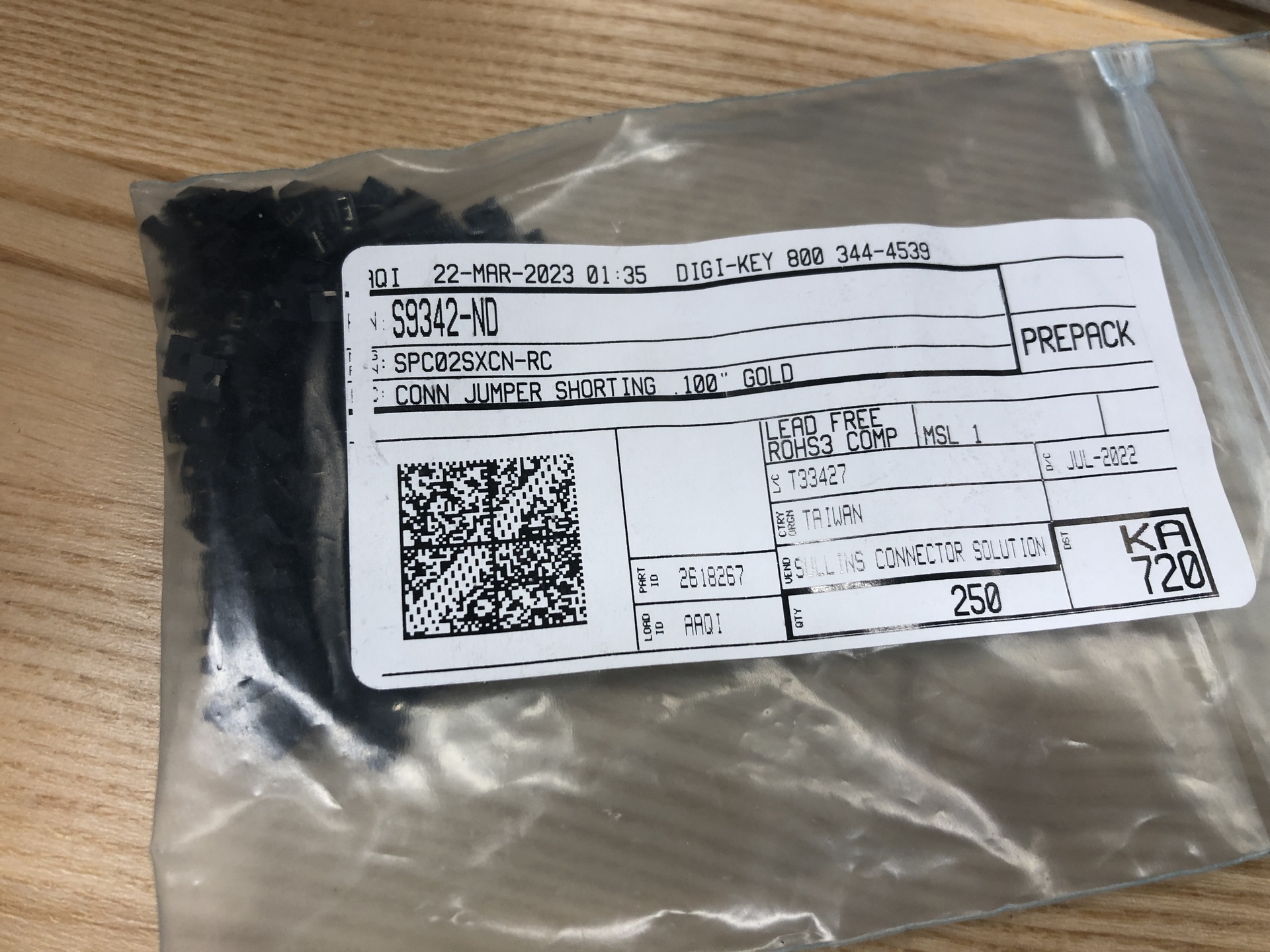
| Jumper Cap (Shorting block) | 1 |
-
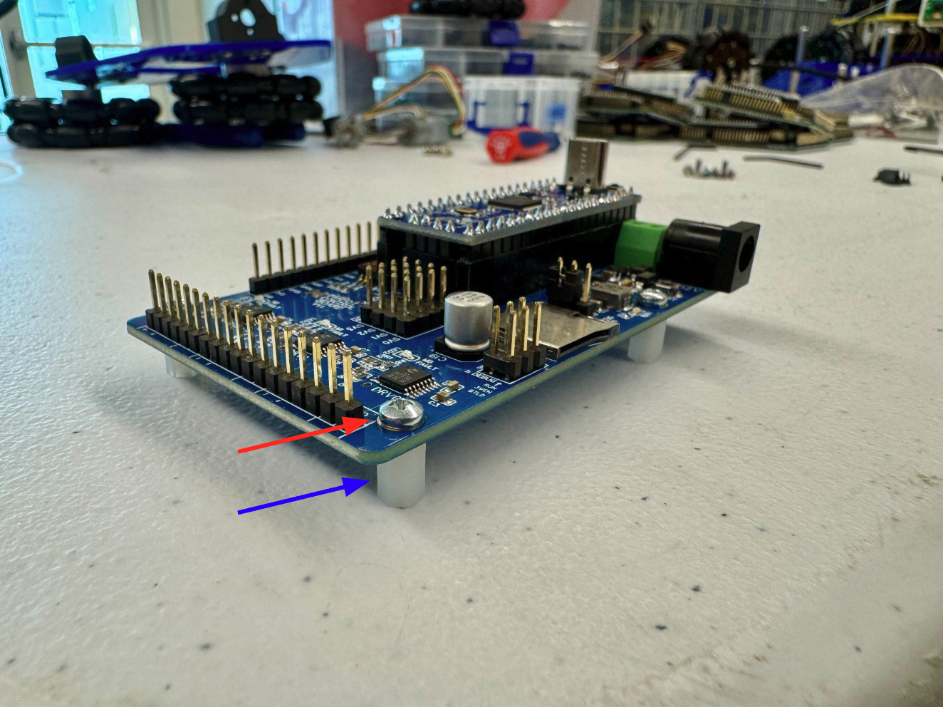
Find the standoffs and screws, and secure them to the holes on the control board.
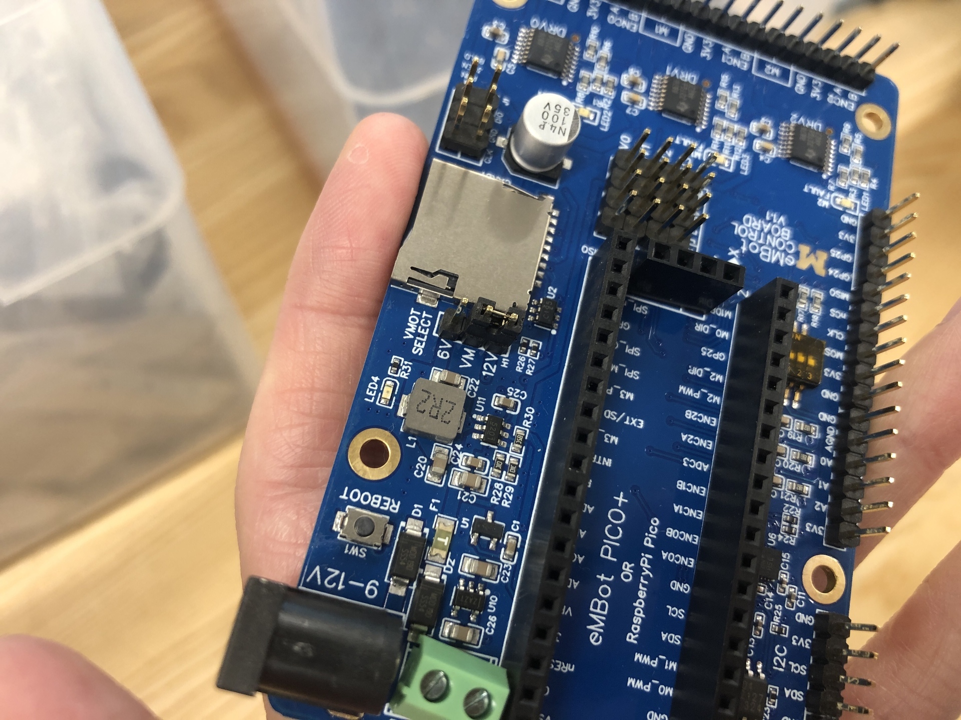
- Put the jumper cap on. Notice that in the 2nd image there are 3 pins squared together. Since we are using 12V, make sure to position the jumper cap over the VM and 12V pins, as demonstrated in the 3rd image.
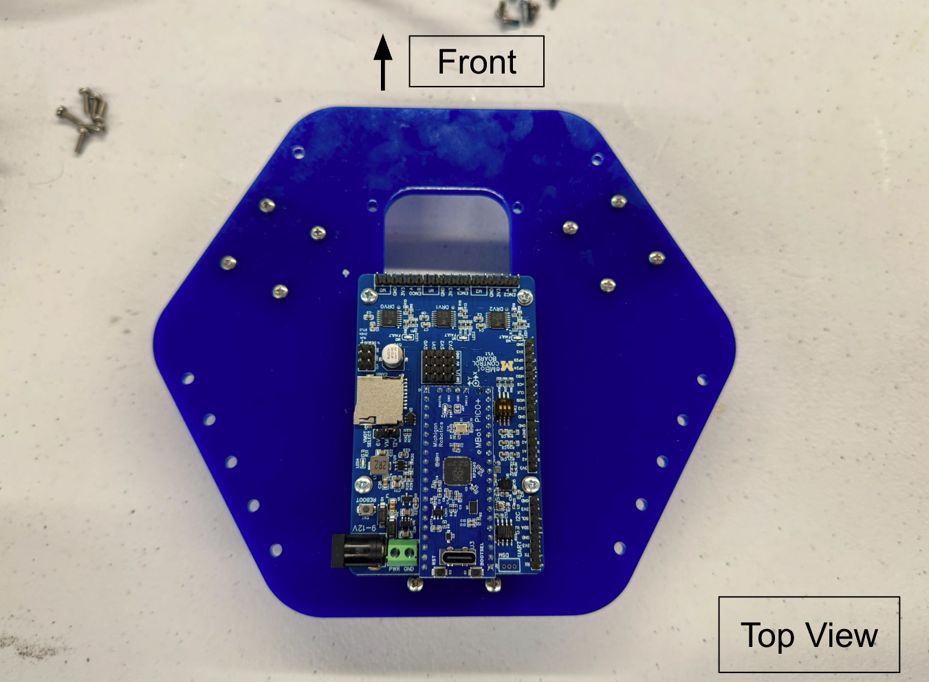
- Attach the control board to the bottom plate like shown in the images below.
4. Attach the motors
| Components | # |
|---|---|
| M2.5x5mm Screws | 6 |
The new 48 resolution motor has encoder pre-attached, which is the one you should use. Don’t know which encoder you have? - Check this page.
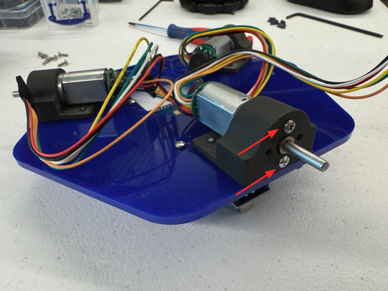
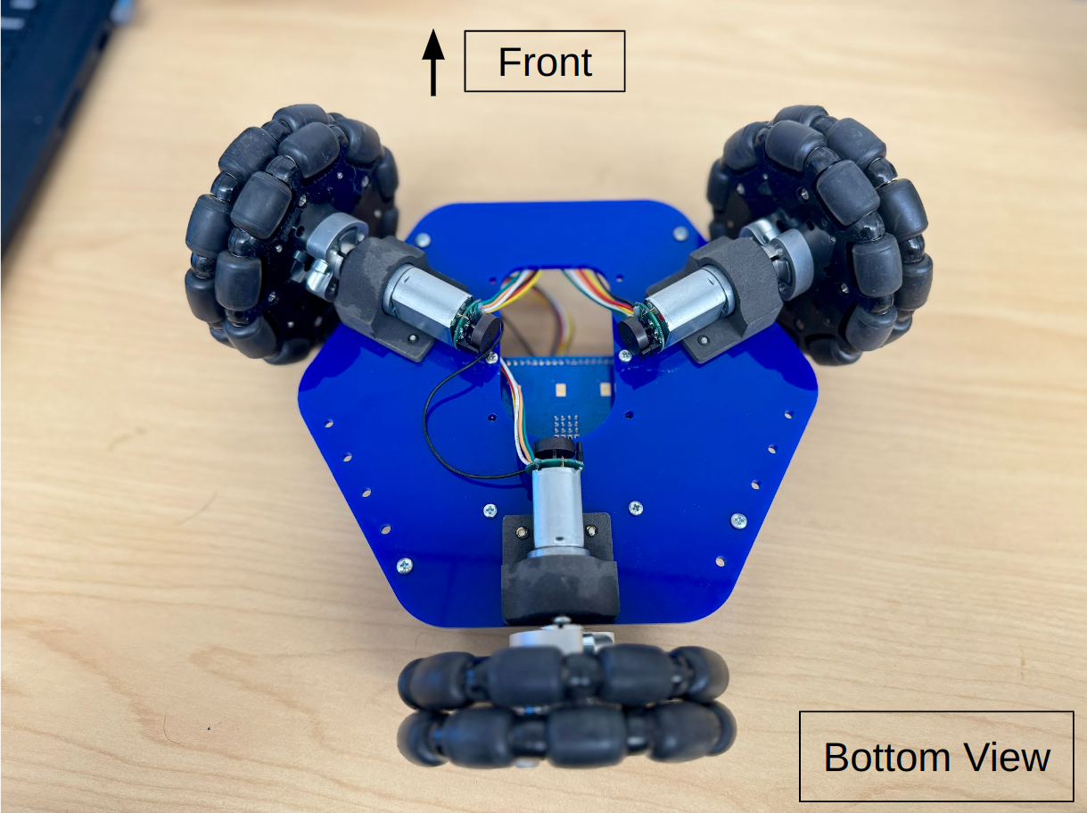
Align the motor’s unthreaded holes vertically with the motor mount holes, secure the motor to the mount using two M2.5x5 bolts, as shown in the image. Repeat this process for all three motors.
5. Attach the wheels
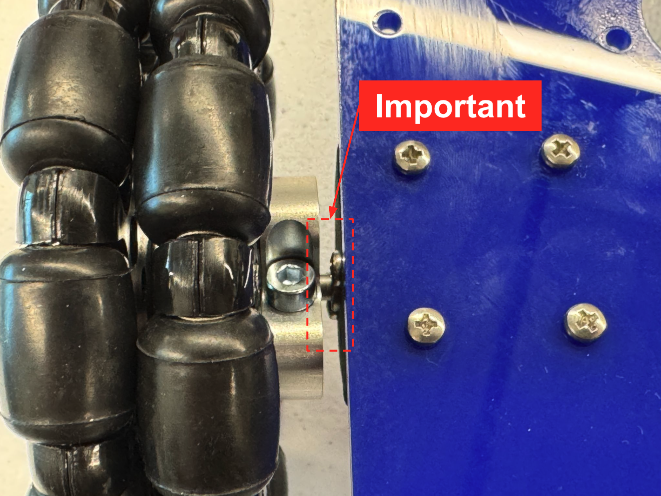
Slide the three (3) Omni wheel assemblies onto the motor shafts, leaving a nominal gap between the couplers and the motor mount screw heads like shown in the first image below, and fasten by tightening the two hex-head bolts on the coupler.
6. Connect motors to the control board
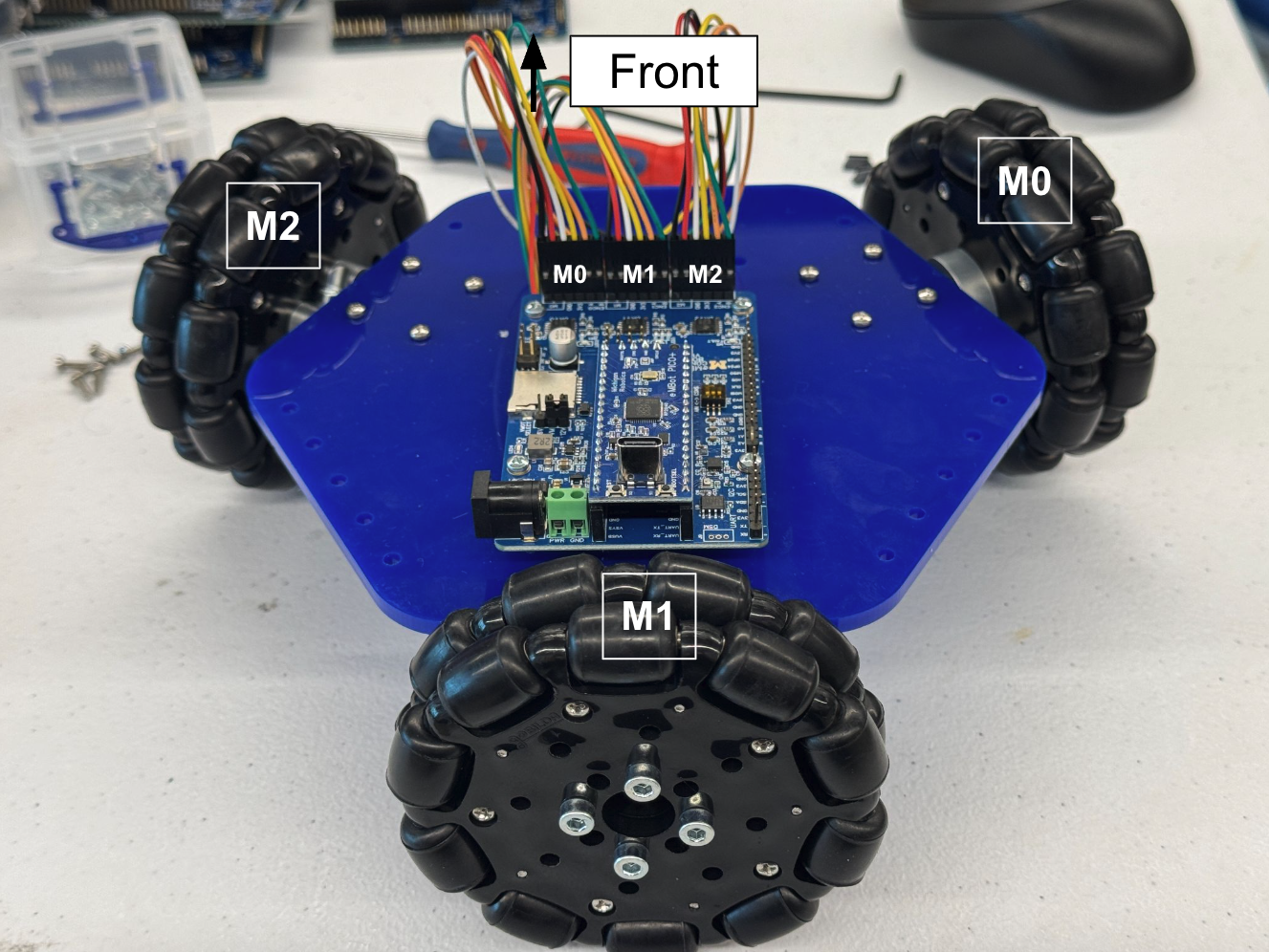
Route the motor wires through the cut-out in the acrylic plate and connect them to the pin-outs on the control board as follows:
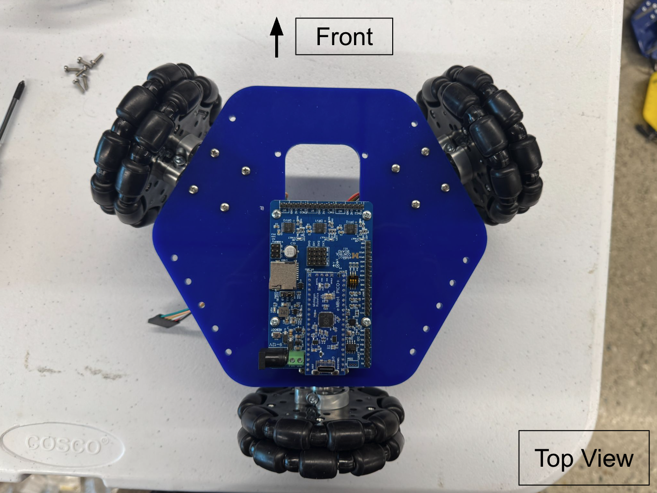
- Right wheel → M0 slot
- Back wheel → M1 slot
- Left wheel → M2 slot
⚠️ Note: Make sure each harness is connected as shown in the image. The white pin must align with the GND pin, which is marked on the control board.
7. Put on standoffs
| Components | # |
|---|---|
| 4-40 x 1.5inch aluminum standoffs | 4 |
| 4-40 x 3/8inch screws | 4 |
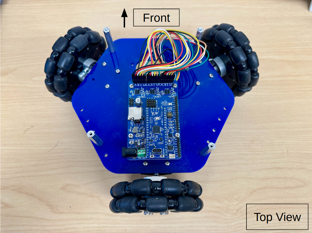
Fasten four (4) #4-40x1.5” aluminum standoffs to the top side of the bottom plate using four (4) #4-40x0.5” bolts. Note that the two standoffs at the back are intentionally asymmetrical—it’s part of the design.
Middle Assembly
1. Prepare the Pi 4
| Components | # |
|---|---|
| Raspberry Pi 4B 4GB | 1 |
| Raspberry Pi Heatsink Case | 1 |
| Raspberry Pi 5MP Camera with Cable | 1 |
-
Carefully peel off the protective plastic on both sides of the thermal pads that come packaged with the heatsink case. Stick them onto the three chips shown on the Raspberry Pi, or directly onto the heatsink. There are 3 spots for the thermal pads and the thermal pads are precut to the required shape.
-
Insert the camera data cable that comes packaged with the camera into the RPi’s camera connector. You will pull up the black plastic clamping piece, and slide the cable in with the metal contacts pointing away from the black plastic clamping piece. Ensure it is properly seated and push down on the black plastic clamping piece to keep in place. You should just barely see the contacts above the top of the connector.
-
Thread the camera data cable through the corresponding slot on the heatsink case top.
-
Screw the bottom of the heatsink case onto the RPi with two of the included M2.5 socket cap screws through holes on two opposite corners of the case. We will screw longer screws into the other two holes to mount the case to the middle plate.
-
With the black piece of the connector pulled out on the camera, insert the Raspberry Pi ribbon cable into the camera PCB as shown (metal contacts facing toward the camera side, blue side on the rear), and then close the black connector.
2. Prepare the camera and camera mount
| Components | # |
|---|---|
| 3D Printed Camera Mount | 1 |
| M2x8 bolts | 2 |
-
Fasten the camera PCB to the 3D-printed camera mount with two (2) M2x8 bolts threading directly into the 3D-printed material (only 2 necessary, diagonal orientation preferred)
-
Insert USB-C-to-USB cable into port on Raspberry Pi as shown
3. Add battery slot
| Components | # |
|---|---|
| Middle Acrylic Plate | 1 |
| Zip tie | 4 |
| battery slot pieces | 5 |
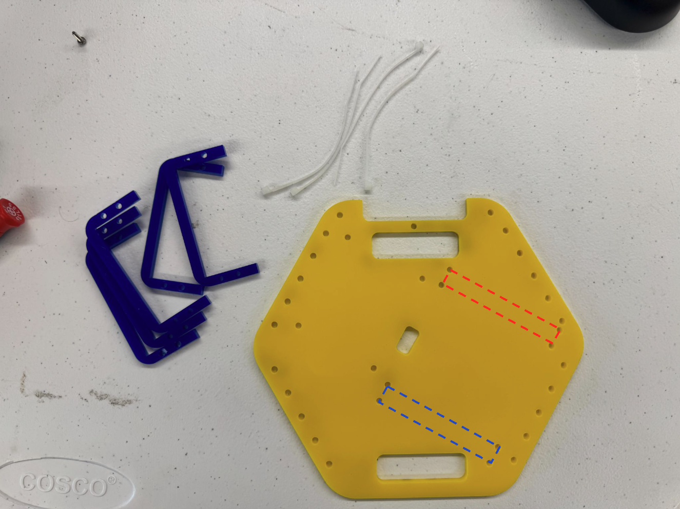
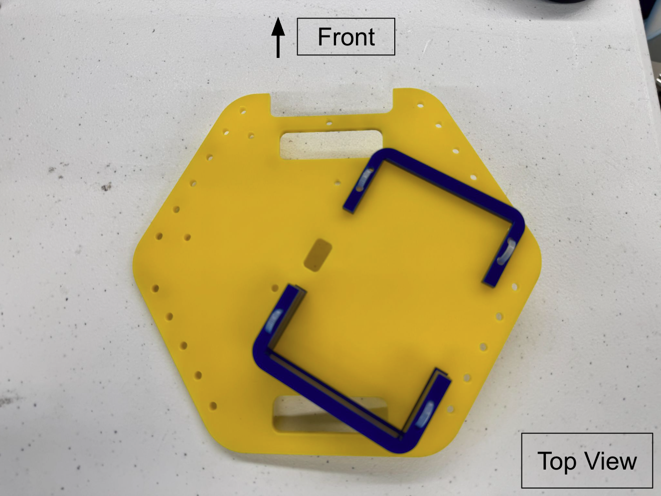
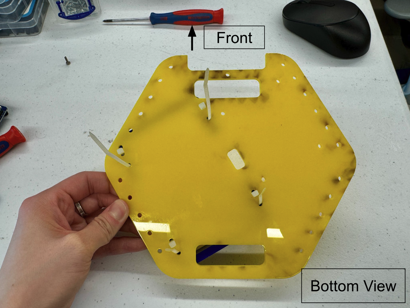
Assemble the battery slot as shown in the images below. Attach 1 slot piece to the area marked with a red square using a zip tie. Stack 4 slot pieces together in the area marked with a blue square.
Next we are going to attach the Raspberry Pi & the Camera to the middle acrylic plate.
4. Attach Pi4 and camera to the middle plate
| Components | # |
|---|---|
| 1.5in Aluminum 4-40 Standoffs | 4 |
| M2.5x20 bolts | 2 |
| M2.5x8 bolt | 1 |
| #4-40x0.5” bolts | 4 |
-
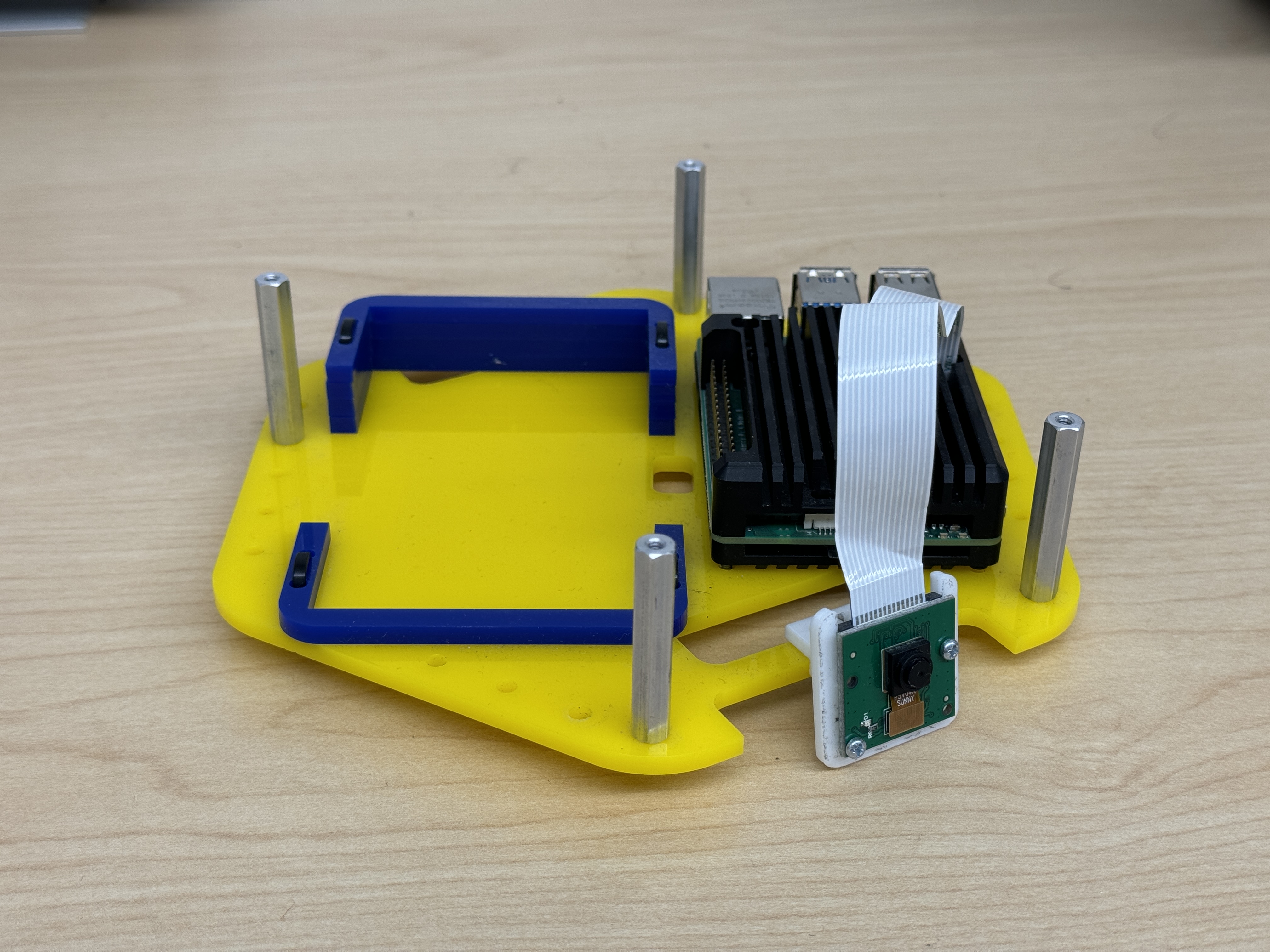
Fasten Raspberry Pi/Camera assembly onto the top of the blue acrylic plate by threading two (2) M2.5x20 bolts from the bottom-side through to the corresponding holes on the Raspberry Pi case/heatsink.
-
Fasten the camera mount to the top of the acrylic plate as shown, with a single M2.5x8 bolt from the bottom-side.
-
Fasten four (4) #4-40x1.5” aluminum standoffs to the top-side of the blue acrylic plate with four (4) #4-40x0.5” bolts.
Top Assembly
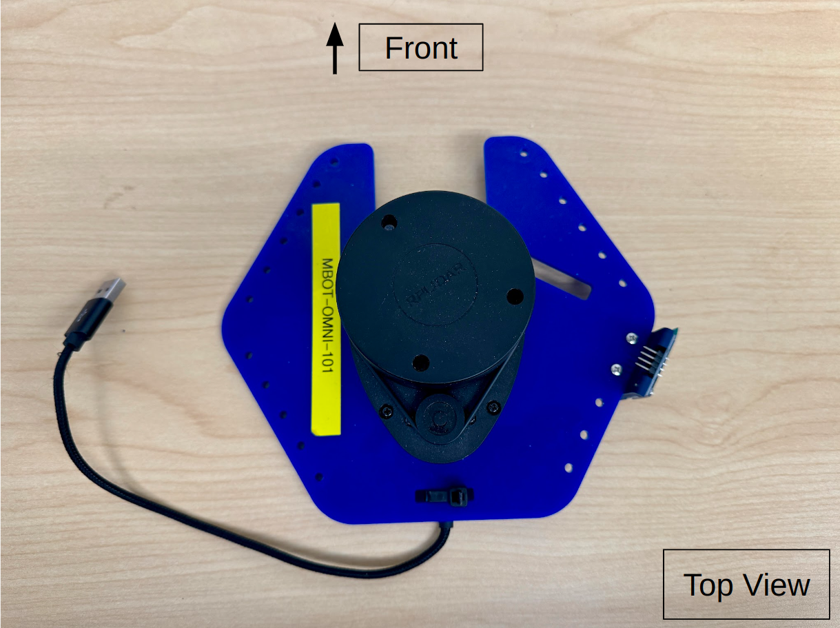
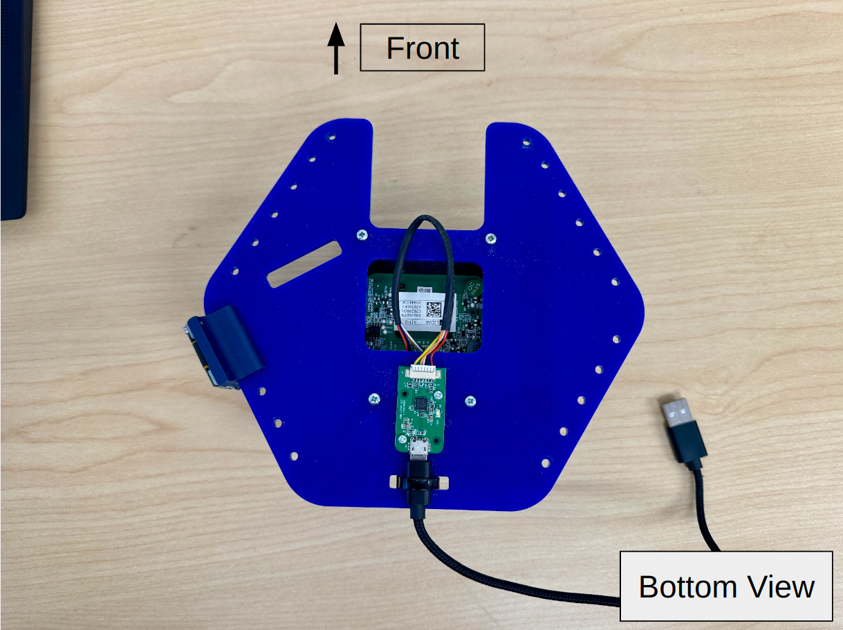
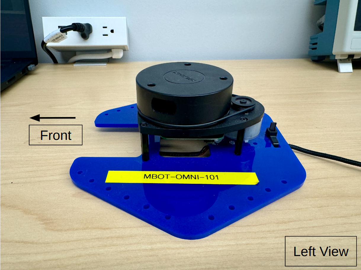
1. Attach the Lidar to the top plate
| Components | # |
|---|---|
| Bottom Plate | 1 |
| RPLidar A1 with USB Interface | 1 |
| Zip tie | 1 |
| Micro USB Cable | 1 |
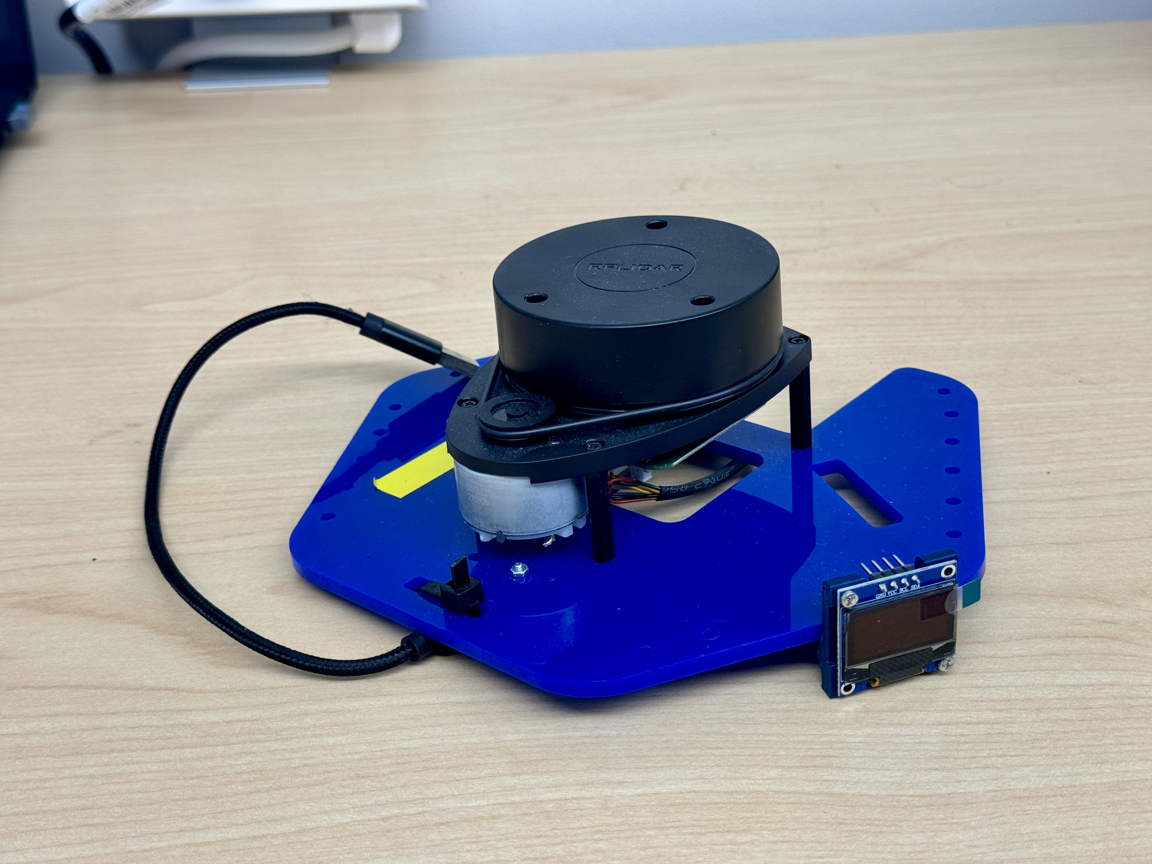
- Fish the RPLidar USB Interface (the little green board with micro usb slot) through the opening in the top plate and align with holes shown in the image.
- Using two M2 screws and nuts, screw the USB interface on the bottom side of the top plate.
- Place the RPLidar on top of the top plate and align with the holes as shown below. Using four 2.5MX8 mm screw, secure the RPLidar to the top plate.
- Attach a MircoUSB cable to the USB interface. Using a Zip tie secure the USB cable to the top plate.
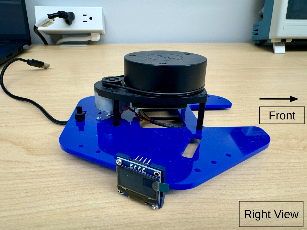
2. OLED Screen
| Components | # |
|---|---|
| OLED screen | 1 |
| OLED mount | 1 |
| M2 x 8mm screws | 4 |
| M2.5 x 8mm screws | 2 |
| M2.5 threaded inserts | 2 |
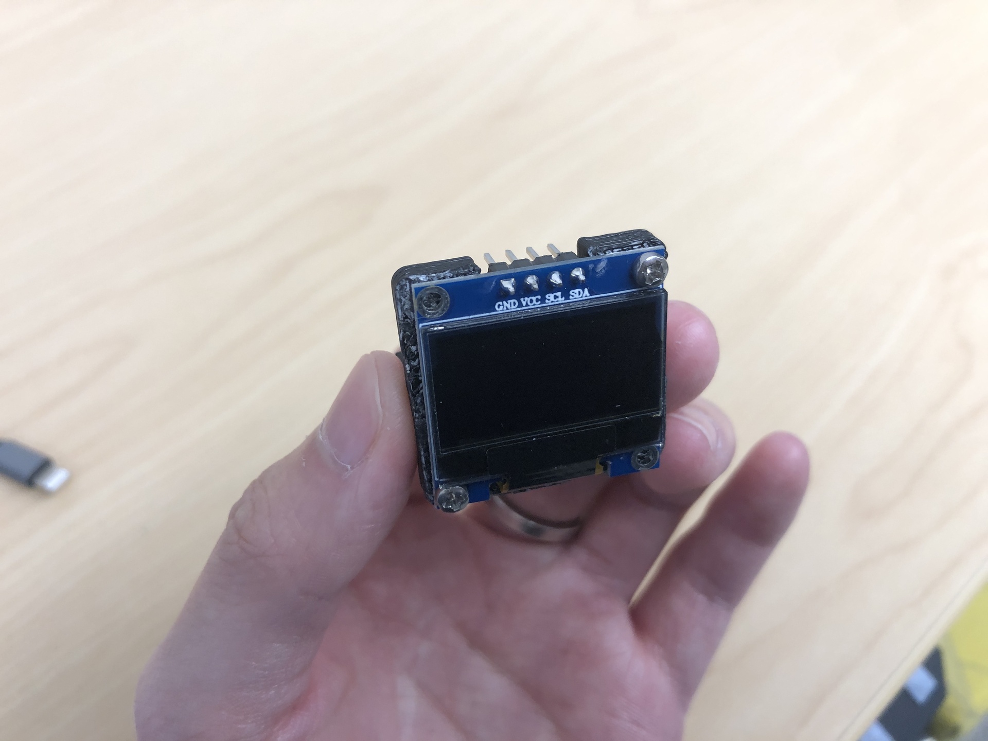
- Insert the threaded inserts into the OLED mount, you need soldering iron for this to heat up the inserts.
- Secure the OLED screen to the mount using four M2 x 8mm screws.
- Attach the mount to the right side of the robot using M2.5 x 8mm screws.
Final Assembly and Wiring
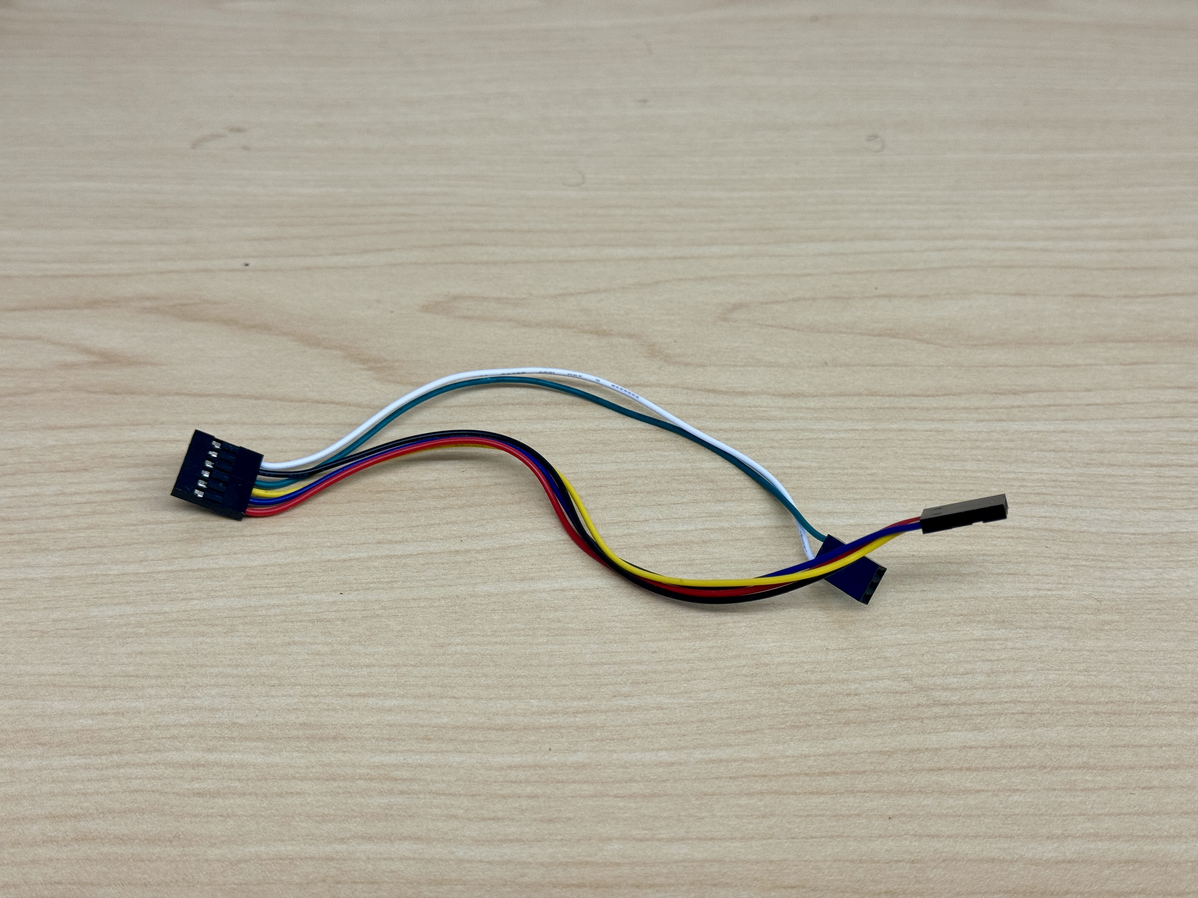
1. Assemble 3-heads jumper wire cable
| Components | # |
|---|---|
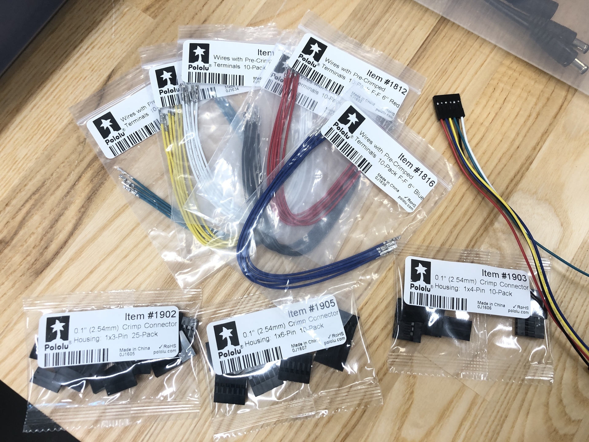
| jumper wires (Black/Red/Yellow/Blue/Green/White) | 6 |
| Crimp connector housings (3/4/6 pins) | 3 |
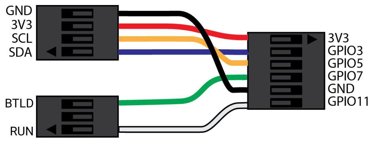
You will need to build the OLED/Bootloader cable assembly as shown. This cable has three heads, which plug into the following:
- Raspberry Pi header (6-pin header)
- OLED module (4-pin header)
- Control board (3-pin header)
This cable allows communication with the OLED and controls the run and bootload modes on the control board.
Assemble the 3-heads wire as depicted in the image. Color and order matters! Your assembled wire should look exactly like the image indicated.
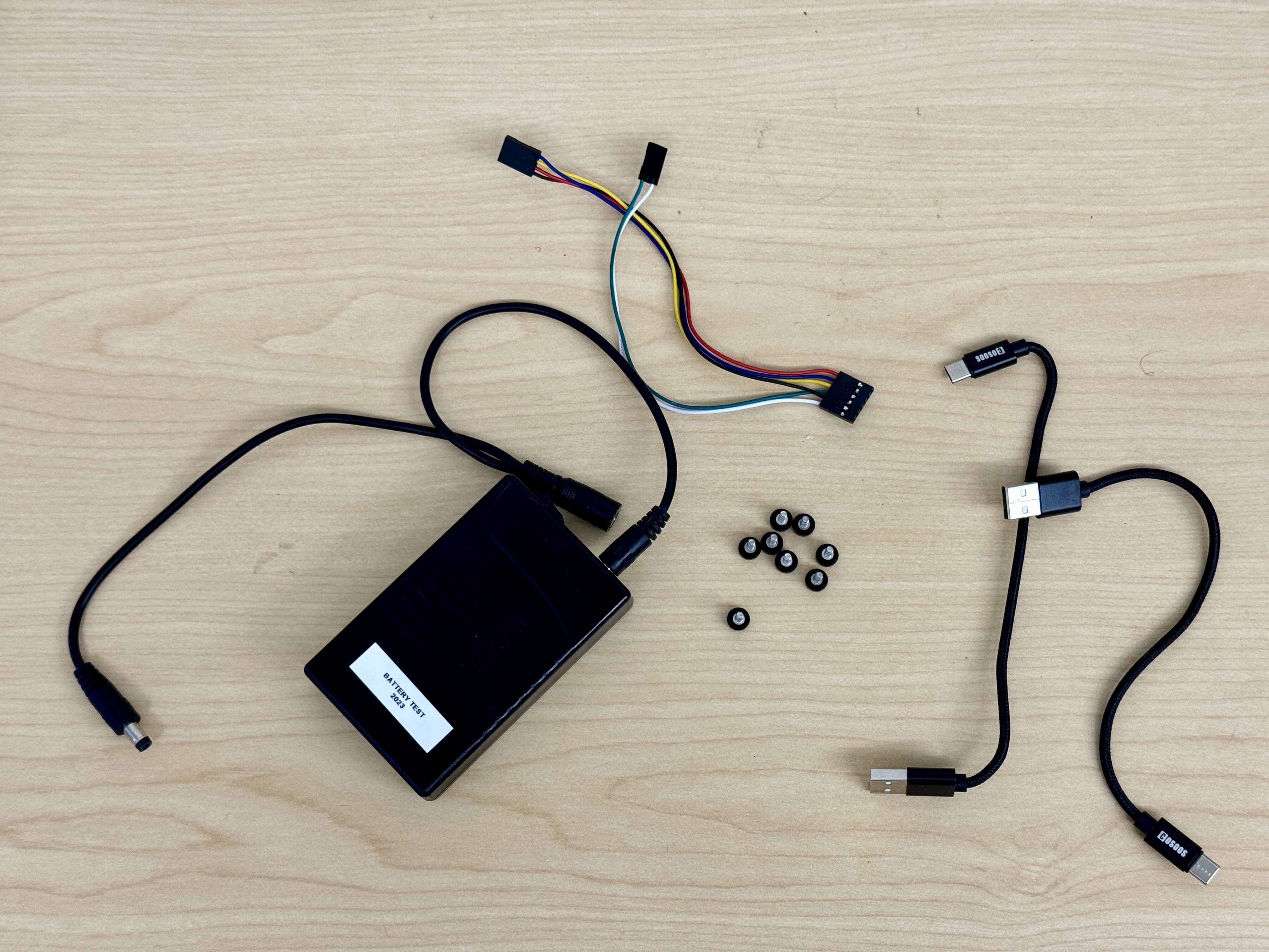
2. Assemble 3 plates
| Components | # |
|---|---|
| Top Assembly | 1 |
| Middle Assembly | 1 |
| Bottom Assembly | 1 |
| 4-40 Thumbscrews | 8 |
| USB-C Cable | 2 |
| TalentCell Battery with Power Cable | 1 |
| Assembled 3-heads jumper wire cable | 1 |
-
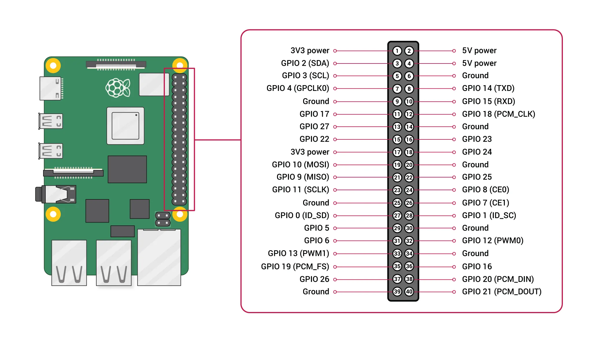
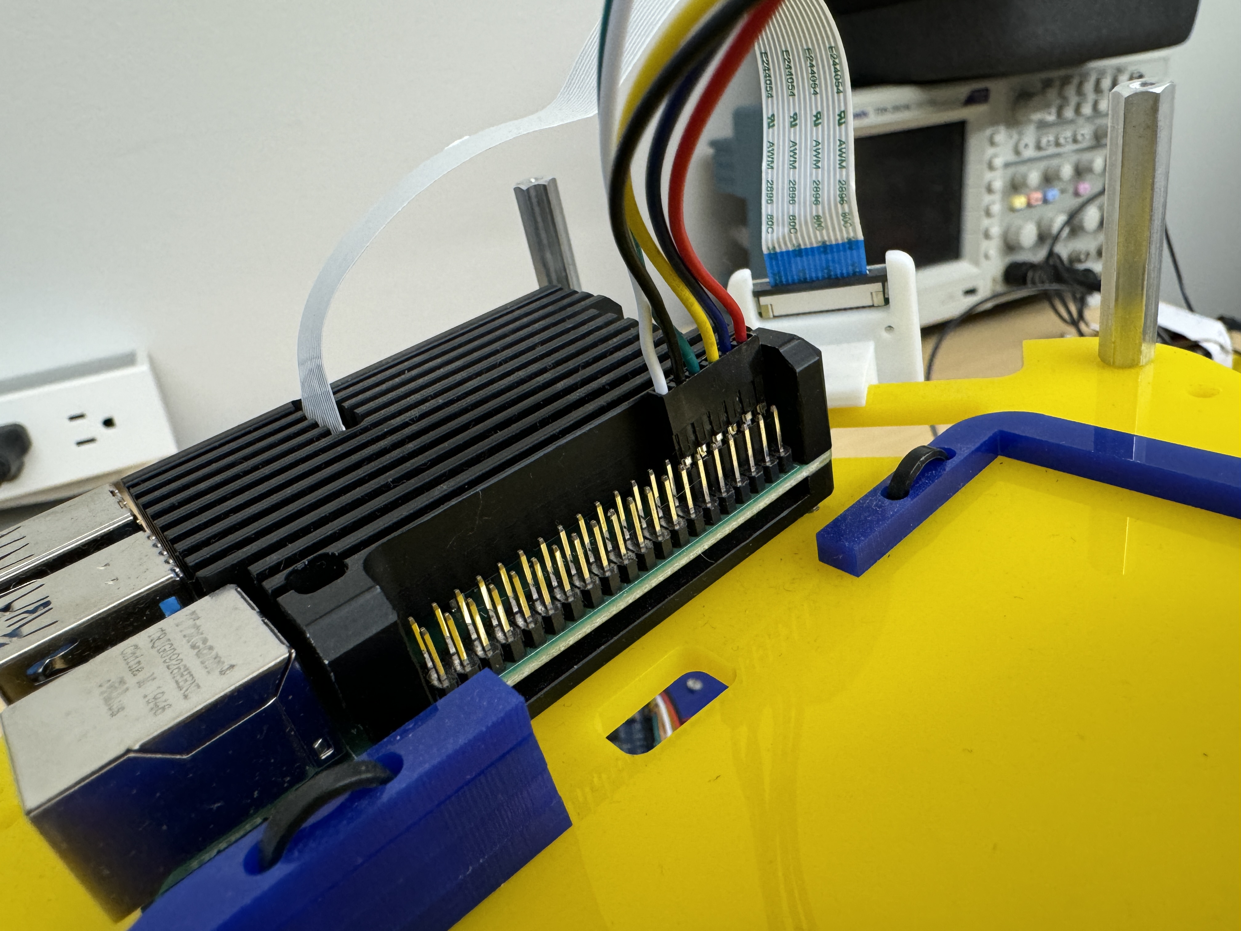
Plug the 6-pin connector into the Raspberry Pi pins.
According to the image below, the red cable should be connected to Pin 1 (the number inside the circle, not the number marked on the side), and the white cable should be connected to Pin 11. Plug into the Pi as shown in the image.
-
(Optional) Pull the 2-pin header thru the hole and plug into the control board. This step is in beta for the automatic firmawre flash method (see link). You’ll get more details about this during the firmware flashing step, so it’s up to you whether to plug it in now or skip it for now.
- White cable to RUN
- Green cable to BTLD
-
Then, use the thumb screws to attach the middle plate to the bottom plate and secure the screws to the standoffs.
-
Connect the 4PIN connector to the OLED, ensuring that the pins align with the marked positions, black wire to GND pin. And also put the battery in the battery slot.
-
Then, use the thumb screws to attach the top plate to the middle plate and secure the screws to the standoffs.
3. Final wiring
-
Connect LiDAR to the Pi.
-
Connect Pi and Pico using USB-C Cable.
Plug the Type A end into one of the Raspberry Pi’s USB ports and the Type C end into the PICO on the bottom board.
-
Connect Pi to the battery.
Plug the Type A end into the battery and the Type C end into the power supply slot on the side of the Raspberry Pi 4. This connection powers the Raspberry Pi.
-
Connect Control board to battery.
Connect one barrel plug to the control board and the other to the battery. This powers the control board.
Now you have a complete version of MBot. You are ready to set up the software and make the robot move!
