MBot Hardware Troubleshooting Guide
When you have calibrated and flashed your MBot, the robot should drive from the web app. While it won’t drive in perfectly straight lines, it should be pretty close!
If your robot won’t drive, or your robot is driving “wonky”, the guides on this page will help you fix it.
Common Problems
One of the wheels is moving too slow
After you calibrate your robot, one problem could be that one or more wheels is driving too slow, causing your robot to drive crooked in one or more directions. If this happens, you might have a problem with how the wheels and motor casing are mounted, or a bad motor. If you are seeing this behavior:
- Check your motor installation, paying special attention to make sure everything is assembled correctly and screwed in tightly.
- Run the test motors script. If one of your motors is not spinning, you should check the connections or replace the motor.
If you found any issues in these steps, try calibrating your robot again and see if the problem is fixed. If you are still having problems, check your encoders.
One of the wheels is moving too fast
After you calibrate your robot, one problem could be that one or more wheels is driving too fast, causing your robot to drive crooked in one or more directions. For example, this video shows a robot being controlled via the web app where the back wheel is turning very fast, causing it to drive crooked when being driven left or right:
The most common cause of this is a bad encoder reading. During calibration, the wheel with the bad encoder spins, but the encoder doesn’t register the movement. The calibration script then determines that it should spin the motor really fast to make it move, since it can’t sense the movement. If you are seeing this behavior, check your encoders, then try calibrating your robot again.
The robot won’t drive
If you are trying to drive your robot and no wheels are turning after you have calibrated and flashed the robot, you might have a problem with the MBot Control Board. Check the board and its connections to fix the problem.
The pi won’t boot up, LED flashing red
The LED light, labeled “STAT,” is located next to the SD slot. “4 long flashes followed by 5 short flashes” indicates “Fatal Firmware Error”. This may happen if the SD card has another operating system flashed on it, causing the Raspberry Pi to boot from it and get confused.
- More error patterns can be found in the official doc.
To solve this issue, you need a SD card reader and a Laptop.
- Download Raspberry Pi Imager from Raspberry Pi Official Website.
- Open the Imager and select the following options:
- Raspberry Pi Device: “Raspberry Pi 5”
- Operating System: “Misc utility images” > “Bootloader (Pi 5 family)” > “SD Card Boot”
- Choose Storage: Select your SD card
- Once the SD card is flashed, insert it into your Raspberry Pi.
- Turn the power on and check if the Raspberry Pi is working:
- External Monitor Method: Connect your Pi to a monitor and power it on. If the screen turns completely green, your Pi is back to life.
- LED Light Method: Power on the Pi and watch the LED. If the green light blinks continuously, your Pi is functioning properly.
Now, you can turn off the battery, and flash the proper image to the SD card.
Always remember to ensure the SD card has the correct image before booting up the MBot.
Checking the MBot Control Board
First, check the connections. You should have the following connections to your MBot Control Board:
- USB connection to Raspberry Pi. You should have a USB cable connecting from the USB ports on the Raspberry Pi to the USB-C port sticking up on the MBot Control Board’s Pico.
- 12V power to the MBot Control Board. You should have a connection from the barrel plug on the MBot Control Board to the barrel plug on the battery pack.
If these are connected and you still can’t drive the robot, try a different USB cable from the MBot Control Board to the Raspberry Pi, then try to recalibrate the robot. If you have verified that the cable is working and you either can’t flash the calibration program on the board or the calibration program does not cause the wheels to spin, replace the MBot Control Board.
If you replace the MBot Control Board, you will have recalibrate and reflash the new board.
Checking Motors
If for some reason your MBot is not moving correctly, ensure that you have properly carried out the calibration steps in the MBot Calibration Guide. During the calibration process the MBot should spin on the spot, first counter-clock wise and then clockwise as show in this video. If you notice any other behavior follow these steps in order to determine the cause of the problem.
Checking Wheel & Motor Installation
NOTE: Disconnect the Lidar USB cable from the Raspberry Pi before continuing.
-
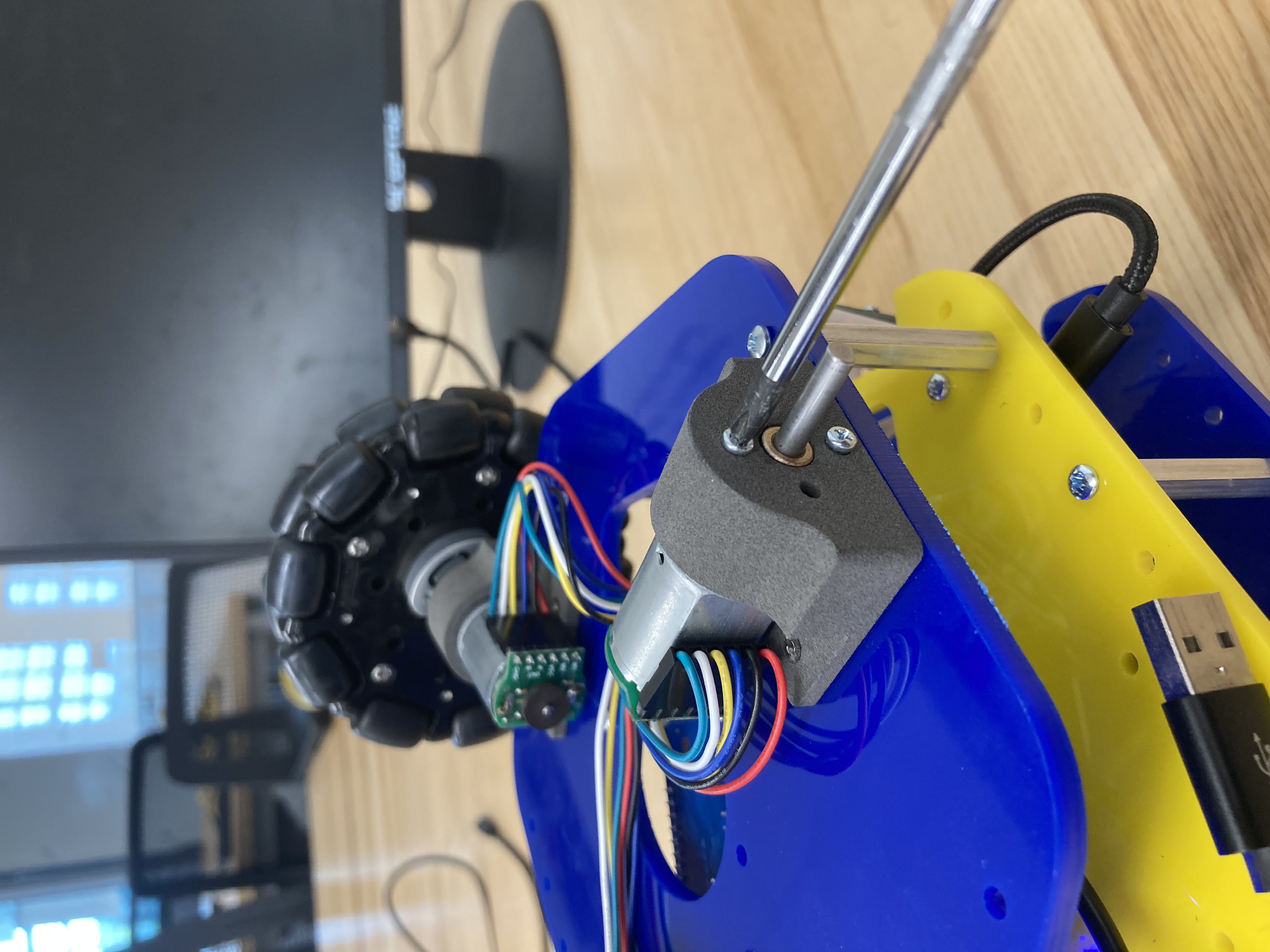
Verify Motor Mounts: At times the motors might come loose from the mounts, for example like this:
If this is the case, take the wheels off from the motor and tighten the screws that secure the motor in the mount.
-
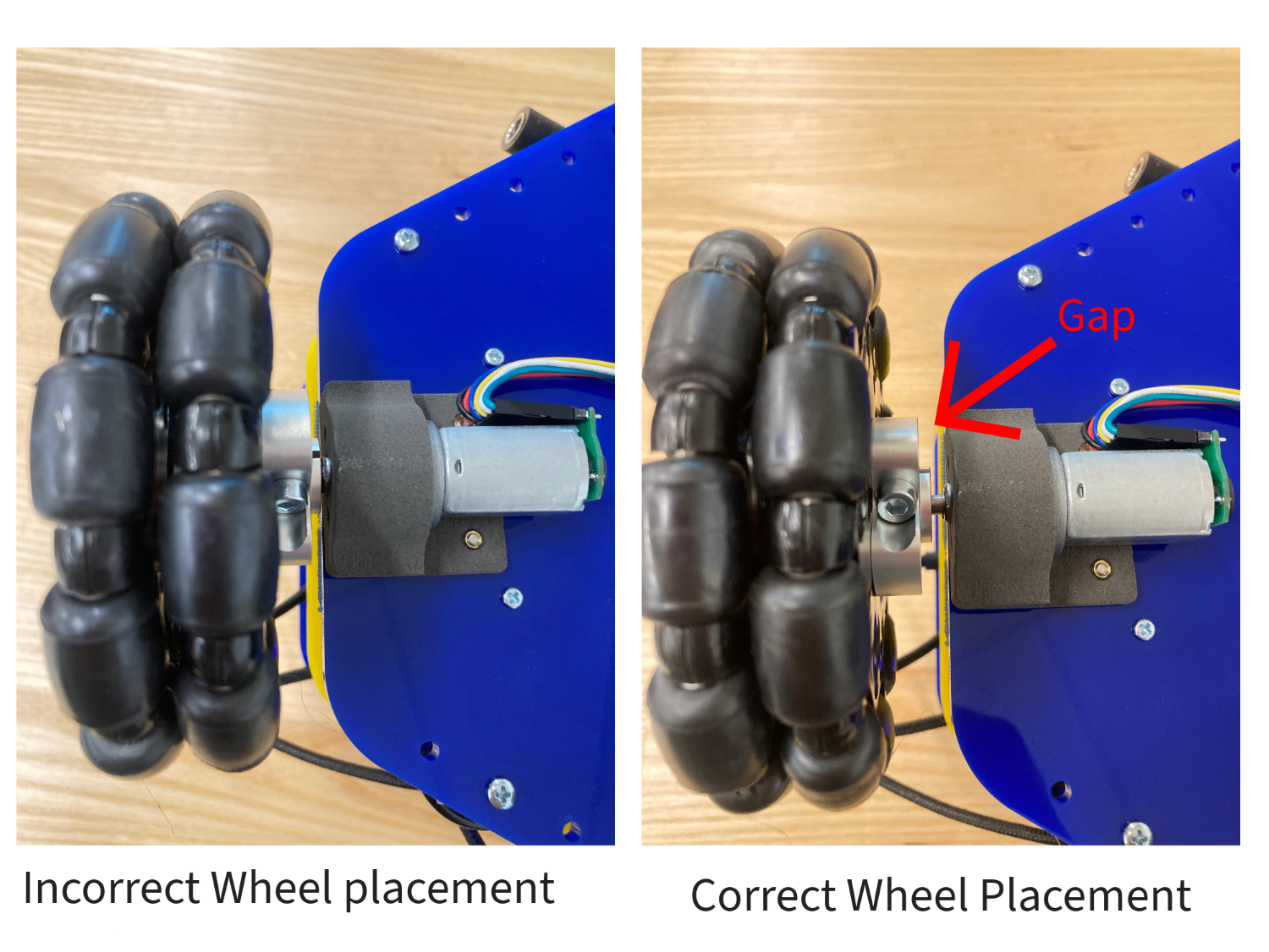
Verify Wheel Hub Placement: Ensure that there is a gap between the wheel hub and screws of the motor mount. Having no gap will cause the hub to rub against the screws hindering the motors from turning properly. If this is the case, you will have to loosen the screws on the hubs and pull out the wheels a little bit to create a gap.
-
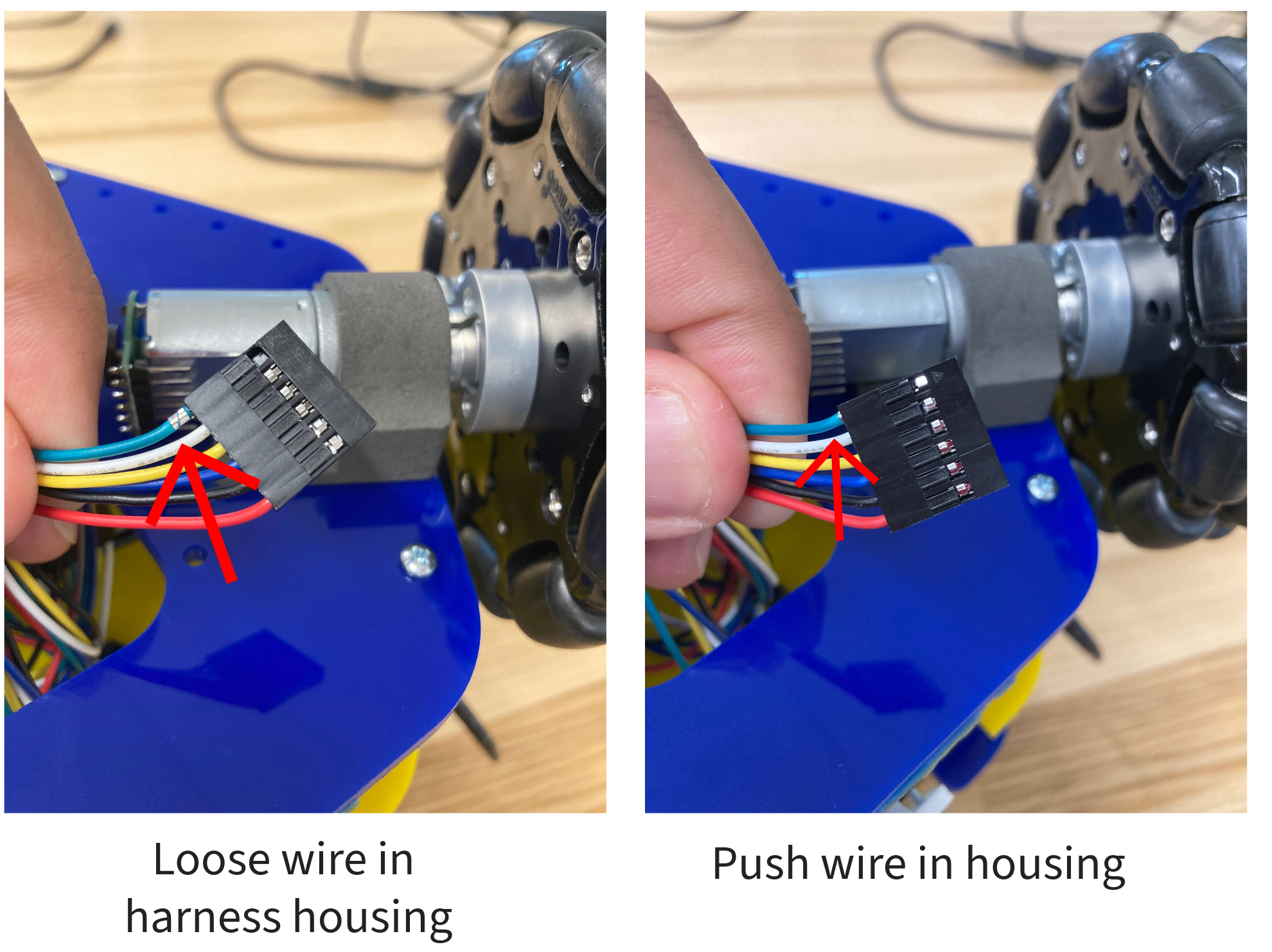
Verify Motor Harness Housing: Sometimes the wires of the motor harness might come loose from the black housing. This will cause an open circuit in the motor harness causing the motors to behave improperly. If this is the case, disconnect the harness from the encoders and push in the loose wires back into the housing. Check all 3 motors harnesses before moving on.
-
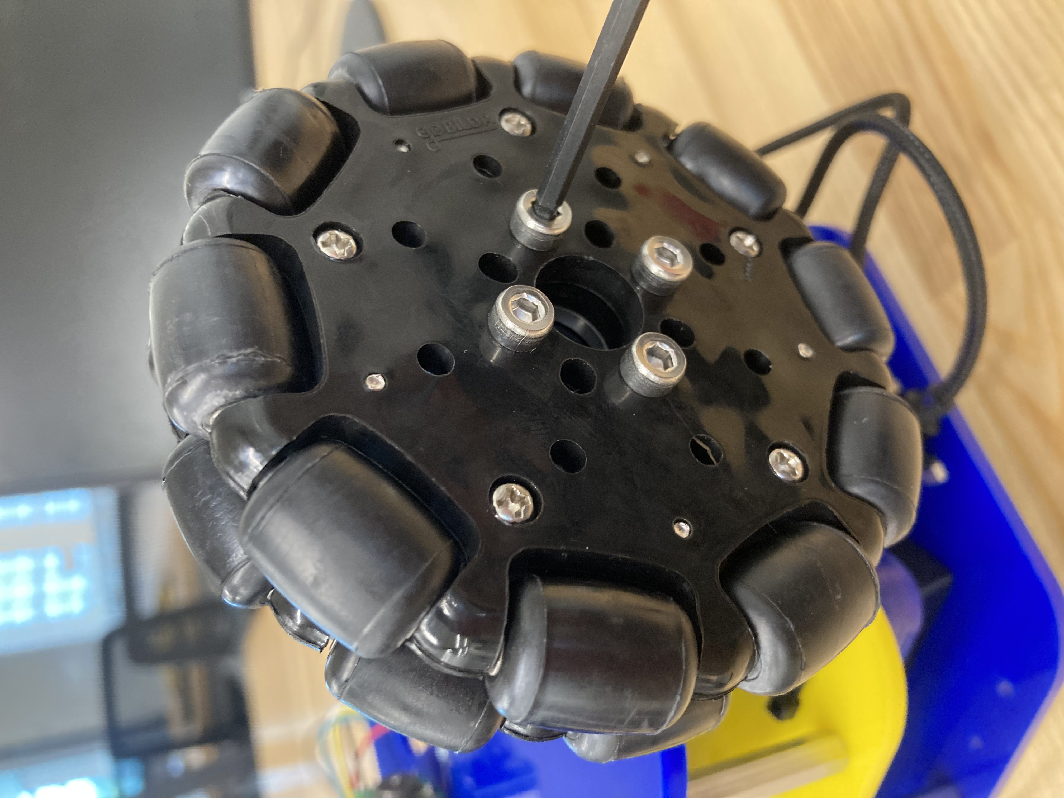
Tighten the Omniwheel Screws: Ensure that the 4 screws holding the pair of omni wheels are secured properly. Do this for all 3 wheels.
Running the Motor Test
Download the motor test file for the Classic or the Omni. Flash this to the Pico and place your MBot upside down. Instructions on how to flash the Pico can be found here. This program will test the functionality of the motors one at a time by spinning them back and forth like this:
If any of the motors fail to spin, you most likely have a faulty motor or motor connector. Check the connection or replace this motor and repeat the Motor Test Program step.
Checking Encoders
If all the motors are working correctly and the MBot still does not move correctly, you might have a faulty encoder. Follow these steps in order to find out which encoder on your MBot is not working correctly.
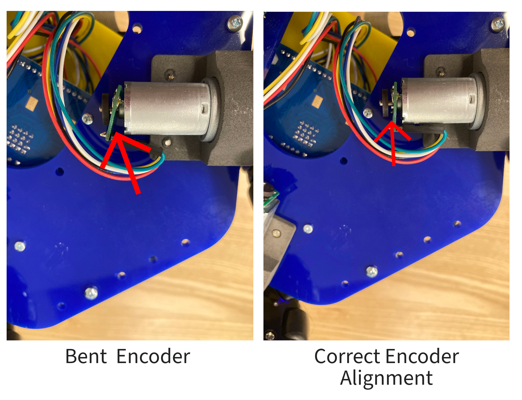
Checking Encoder Installation
Sometimes the encoder on the back of the motors might bend causing the friction between the PCB and magnet. Ensure the encoder is flat and that there is a small gap between the magnet and the PCB. You may have to use the pliers to pull out the magnets away from the PCB.
Running the Encoder Test
-
Flashing Encoder Test Program: Download the
mbot_encoder_test.uf2file from here. Flash this to the Pico and place your MBot upside down. Instructions on how to flash the Pico can be found here. -
Open a Terminal: From a session connected to your robot (use either VSCode or NoMachine), open up a terminal. This is where we will test all the encoders.
-
Start minicom: In the terminal type
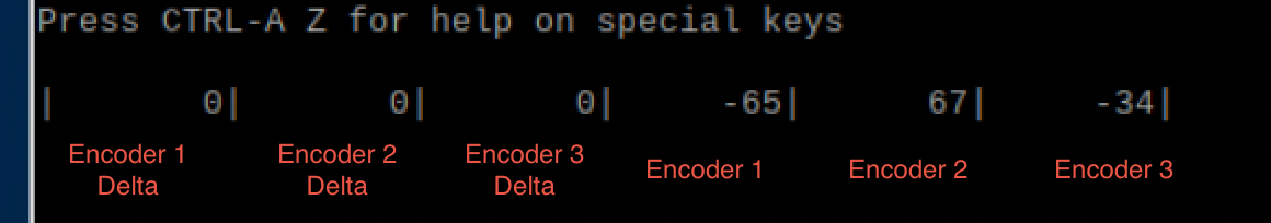
minicom -D /dev/mbot_ttyand press enter. This will bring up the following screen: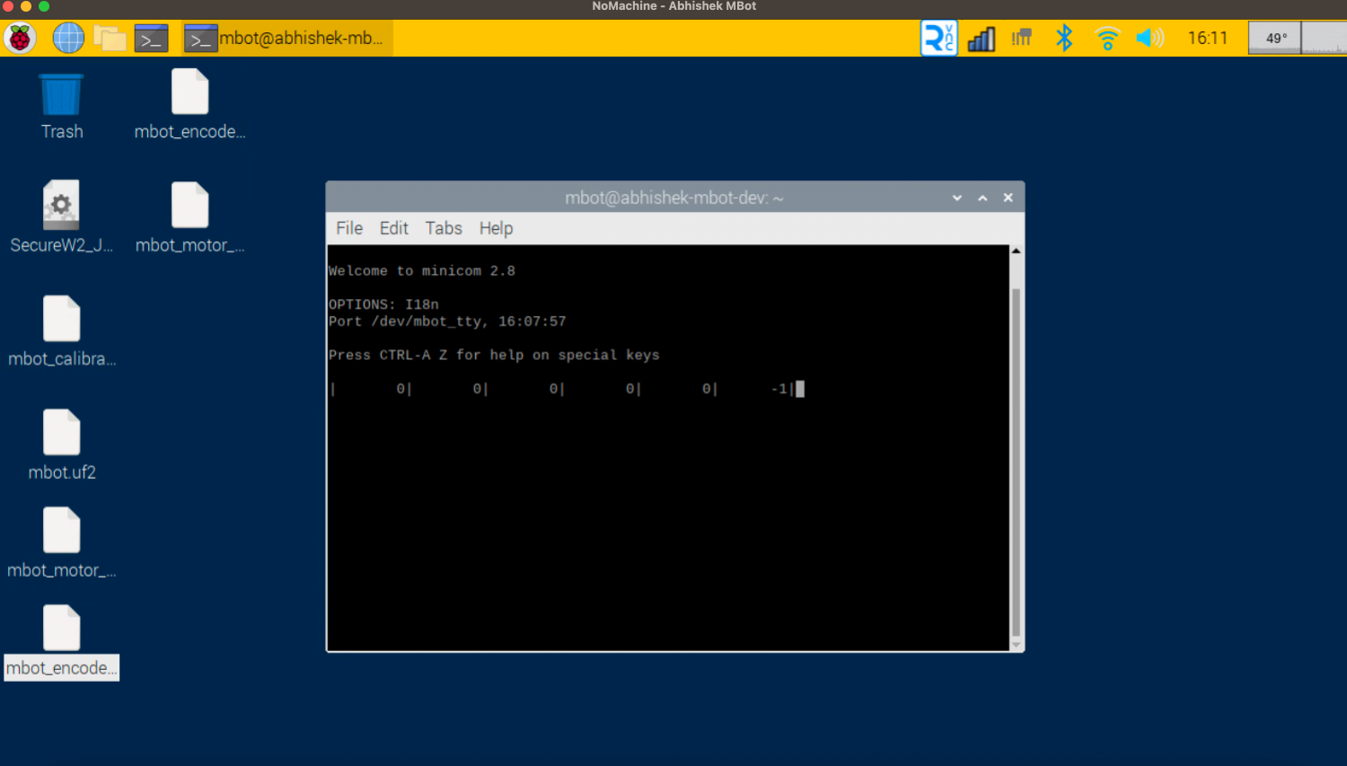
-
Reading Encoder Values: You will notice there are 6 numbers on the screens. The first 3 numbers represent the delta values of each of the encoders i.e. the instantaneous change in the encoders values. While the last 3 numbers represent the total ticks for each of the encoders.
-
Verifying the Encoders: One by one, rotate each wheel manually and carefully observe the changing values in the terminal. As you rotate a wheel, you will notice that the total value for each encoder will increase when you turn it in one direction, and decrease in the other.
One of the encoders not changing? If one of the values is not changing, you may have a bad encoder. Check the cables first, and if that doesn’t help, replace the motor.
You can watch this video which shows the behavior of step 5. If you do not see this on your MBot, then you have a faulty encoder and you will have to replace the both the motor and the encoder.
Checking the Encoder Readings
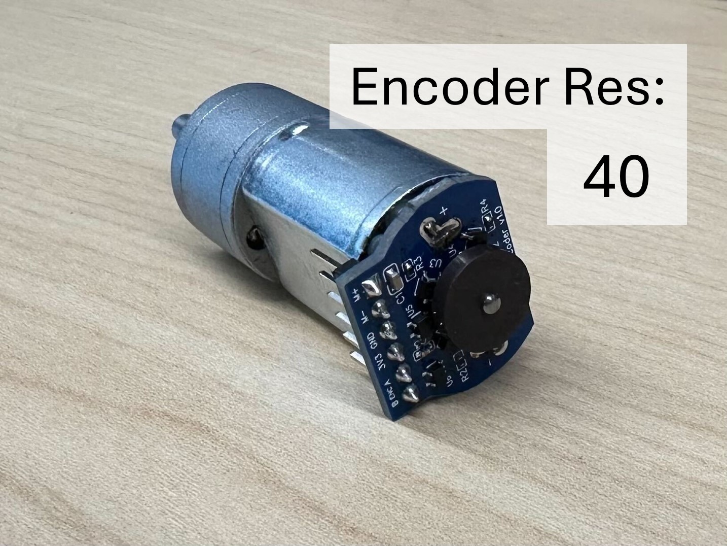
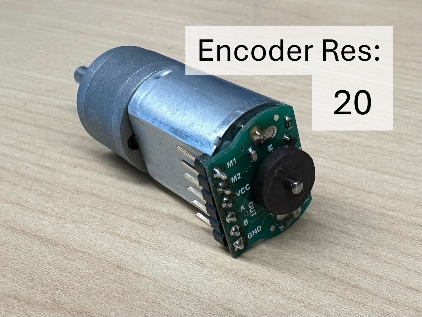
If you have the style of encoder with the sensor on the circuit board, as in the last two pictures below (resolutions 20 or 40), one common problem is that the black magnetic encoder wheel is mounted incorrectly on the shaft of the motor.
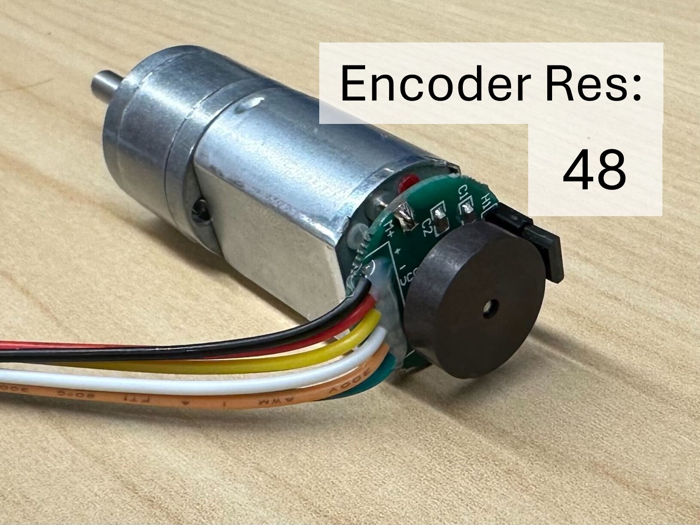
Note: If you have the style of encoders in the first picture (resolution 48), this problem is very unlikely! You can still test the readings, but moving the encoder up or down the motor shaft will not help.
If all your encoders are reading values, the next step is to check that the values are all correct. Follow these steps:
- Press the “RST” button on the Pico to reset the values of the encoder readings back to zero.
-
Turn each of the wheels exactly one rotation.
Tip Use a piece of masking tape to mark a point on the wheel to help you turn it one rotation as precisely as you can.
You should see that the number of ticks on each encoder is fairly similar. If one is lower than the others, the encoder magnet may be slightly too far away from the sensor.
The fix: Use your fingers to gently push the black magnet closer to the board (but don’t let it touch the board). Then, try the test again and see if the problem is fixed.